Secret Reference Line Faces
The open source space around the Revit API is continuously growing richer, solutions are shared and exciting discoveries are made, both in the Revit API discussion forum and elsewhere:
Debugging, Code Signing and HOK Mission Control
Yesterday I happened to notice a tweet by Konrad Sobon, @arch_laboratory, pointing out a couple of exciting blog posts on archi+lab, e.g.:
- Debugging Revit add-ins
- Code signing of your Revit plug-ins
- Playing with Power Shell commands and Post Build events
The latter one discusses some aspects of the Mission Control repository and making it easier to pull, build, and deploy.
In fact, it is worth while taking a look at all the open source HOK Revit Addins.
This is all very exciting stuff indeed.
Browsing further, I also discovered that Konrad just started the next chapter of his career.
Congratulations, Konrad!
The best of luck to you, and have fun!
Creating Connectors on a Reference Line
MarryTookMyCoffe points out a surprising and useful possibility for creating connectors on a reference line:
I made some tests and thought I will share my results with the forum:
The problem with putting connectors on a reference line is that the API doesn’t give us any references to any surfaces, no matter for what view we ask.
There is however a way to get around this one by adding a secret suffix to the unique id and calling the ParseFromStableRepresentation method on it:
  Reference.ParseFromStableRepresentation(
    document, uniqueID );
With the right secret suffix, this can be used to retrieve a reference to a face on the reference line.
With lots of trial and error, we learned that the codes for specific faces will be always the same:
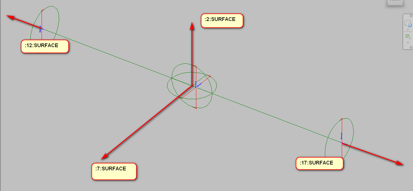
For example, let's look at this stable representation:
3ded2a48-367f-42c7-83bd-9fd4f659891a-00000fd0:2
Here is a table summarising the possible secret suffixes:
| 3ded2a48-367f-42c7-83bd -9fd4f659891a-00000fd0 | The Reference Line unique id |
| :0 | ref to line |
| :1 | ref to solid |
| :2 | ref to face |
| :7 | ref to face |
| :12 | ref to face |
| :17 | ref to face |
The gaps between the numbers may seems strange, but I think that after every face, we have hidden edges of this face; what would explain the numeration.
[Q] Does that apply to each and every reference line?
[A] Yes, it applies to every reference line, always the same numbers.
[Q] So each reference line implicitly defines a solid and four faces?
[A] Faces are in the solid, but yes.
[Q] What solid is that?
[A] Similar to an extrusion, you can get a solid of the object with faces and lines, with the only difference that its faces don't have references. I guess the programmer forgot to set up this property.
[Q] Can you share a concrete use case for this?
[A] I use reference line with connectors in all fittings and accessories; that enables my family definition to work with minimal graphics. That way, you can easily define a family with low details (that is important in GB) and high details (that is important in Russia), without messing up how they work.
I plan to go even further and implement an auto-creation tool for fittings, accessories, and mechanical equipment.
The idea was to add to any family made on the market the same functionality that our families have – all you have to do is set length and type of connection, like: thread, pressed, etc.
Very many thanks to MarryTookMyCoffe for discovering and sharing this valuable insight!