Tailor Your BIM with F#, Forge, IFC and Takeoffs
I have a whole bunch of exciting overdue topics lined up.
Let's start with these:
- Tailor Your BIM sums room areas with F#
- Control view for design option elements with F#
- Copy legend view and component from background file
- Forge RVT to IFC translation defaults to 2x3
- Latitude and longitude in Revit IFC export
- Takeoff creation requires branch duct
Tailor Your BIM Sums Room Areas with F#
Ching-Hua Chen shared several nice F# Revit API macros on his blog Tailor Your BIM.
As you know, the .NET framework enables you to use any supported programming language you like, and F# is a fully viable option with some advantages.
Ching pointed out his blog and new post in the Revit API discussion forum thread on efficiently finding the sum of room areas with F#:
While working on Revit, I noticed there could be a few possibilities to improve the efficiency when retrieving the sum of room areas by writing external commands. I posted an external command with F# and Revit API that instantly reports the sum of selected room areas. I would like to share this knowledge with you:
- Find sum of room areas / 空間面積總合
(alternating Chinese and English text)
This solution also addresses a related thread in the Revit Architecture forum on finding the sum of areas.
Control View for Design Option Elements with F#
Ching followed that up with a second post on an efficient control view for Design Option elements with F#, saying:
After the last post about efficiently find the sum of room areas, in the new post, we'll see how to control the colour of the elements within Design Options in the active view:
When we work with design options in Revit, we often have more than one design option group in the same model file. By default, in Revit 2017, I haven't found a way to display them distinctively in the view. Writing a small external command as posted here might help at work.
Many thanks to Ching for these nice contributions!
Copy legend view and component from background file
Håvard Dagsvik shared a new suggestion for creating a legend view in a comment on duplicating a legend component:
Old post and still no methods for creating legend views and components.
But it can be done by copying a legend view and component from a background file using ElementTransformUtils. In the background file group an instance of a legend component. Copy the GroupType and the legend view from the file. Once copied place the GroupType in the copied legend view and ungroup it.
Ungroup will leave you with a 'new' legend component in your new legend view.
This way you can create a legend view incl. component from scratch.
A bit of a hack but it works.
Answer: Yes, sorry that nothing has happened yet in this area.
I have collected a bunch of existing wishes for this and submitted them in the wish list item CF-4442 [API support for legends -- 07320991].
Have you checked whether a wish list item for this functionality has also been submitted to the Revit Idea Station?
That is one of the main driving forces for setting priorities on developer wishes.
Please do so, submit it if it does not exist, vote for it if it does, and let me know, so I can add that input to the development issue as well.
Response: The biggest wish regarding legends would be to add support for using standard tags on Legend Components. So, a Door Tag for a door legend, etc. It's the one thing I've been checking in new Revit versions since 2009. Basically, be able to tag the Type Properties of a component. A couple of threads on that here:
Here is the API request
Many thanks to Håvard for his valuable input.
I added his notes to the wish list item as well.
Forge RVT to IFC Translation Defaults to 2x3
Now for some IFC related notes.
Question: Regarding translation of RVT to IFC via Forge Model Derivative: are there any known issues, limitations or good practices, pls?
Answer: The Revit extractor will look for saved IFC Export Setup Options stored in RVT files including built-in and user created setups to do the RVT to IFC translation.
They can specify a name of the IFC export settings in the output.advanced.exportSettingName field of the POST body while calling the Forge MD POST Jobs API.
Currently, user modified IFC Mapping Files are not supported.
However, there is currently a known issue with the output.advanced.exportSettingName. Unfortunately, the specified IFC Exporting option will not be assigned properly to the Revit extractor. Afaik, we can currently only get the file exported in the default IFC 2x3 format.
Latitude and Longitude in Revit IFC Export
Here is another little IFC related issue, while we are at it:
Q: How is the lat/long information from an IFC exported from Revit read by Navisworks?
This image shows what we see in Revit and how it shows up in Navisworks via the IFC export:
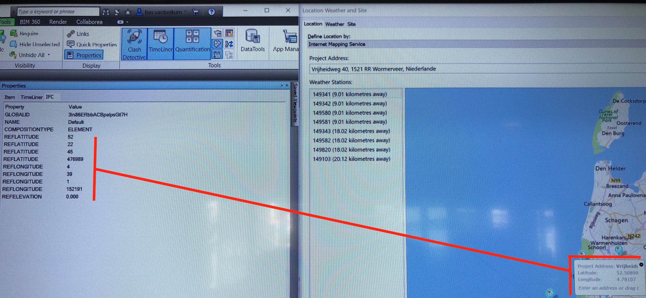
How is this information exported to IFC? Is any formula applied to these values?
Answer: Lat/long is stored in IFC as a quadruple of integers: degrees, minutes, seconds, and millionths of a second.
The fourth value is new to IFC2x3 and was added after a request from us.
Navisworks seems to just be displaying the raw values.
Maybe Navisworks needs to parse this information more correctly.
Takeoff Creation Requires Branch Duct
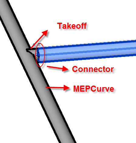
Question: I want to programmatically connect a takeoff fitting onto the body of a duct, the other end of takeoff may or may not be connected to another duct's connector:
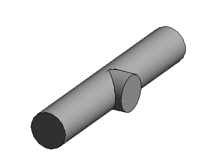
In this image, I draw a 12' long and 2' diameter duct from (0, 0, 0) to (12, 0, 0) at 3' height and attach a takeoff to the middle of this duct.
That gives the following connector locations on these two elements:
  TAKEOFF
    connector #1: (6, 1.3333, 3)
    connector #2: (6, 1, 3)
  DUCT
    connector #1: (12, 0, 3)
    connector #2: (6, 0, 3)
    connector #3: (0, 0, 3)
I've noticed that the duct in the image by default has two connectors which are connector #1 and connector #3. The connector #2 is added when connecting with a takeoff.
What are the steps to attach a takeoff fitting onto a duct body by using Revit API?
Answer: Have you looked at the AutoRoute sample in the Revit SDK, and tried using NewTakeoffFitting instead of NewTeeFitting?
Response: Yes, I looked at these functions. NewTakeoffFitting requires a Connector and a MEPCurve as arguments; both cannot be null, otherwise it throws an ArgumentNullException.
In example above, I purposely draw a takeoff which only attaches to one duct and does not connect to another duct or fitting (Connector). Revit allows the creation of systems like this. Do API functions allow me to create this as well?
Answer: How did you create that tap in the UI? I don't think that Revit will let you place a tap fitting connected on a duct without actually routing a duct, and I think the API has the same limitation.
Response: One way is to make sure the routing preferences uses tap, draw two connected ducts so it creates a tap, then delete one duct. I have not tried to connect a takeoff directly on the body of duct, not sure if that can be done.
My task is to capture the state of the user's design and enable the user to restore and recreate the exact same design and same drawing later reading back the data we stored. The user's design may not be the final design yet, so the source drawing can be anything that Revit allows. So, what is shown on the image is a valid drawing that our plugin needs to recreate on a project drawing.
I can handle other fitting types when they are not connecting to other element on some of their connectors. When the connection is needed, I just call Connector.ConnectTo. I am not sure what to do with takeoff when it needs to attach to a duct body at a location like that.
So, right now, our plugin handles takeoff in special condition. I use the NewTakeoffFitting function to create it, but if it does not connect to a duct body and another connector, the plugin will just not draw it at all.
Maybe the other question to ask is: when can I use the API to create the third connector in a duct element without breaking this duct into two?
Answer: I think you'll have to do as you suggest: route a branch duct to create the tap off the main, then delete the branch duct. When you place a takeoff fitting, it should be creating the third connector, and not break the main into two pieces.
Response: Which API function is used to create the third connector in a duct for the case above?
Answer: Revit handles the curve connectors automagically. Any time there is a tap on an element, the third (or additional) connectors are added. When the tap(s) are removed, the connectors are automatically removed. I wouldn't expect there to be a way to add/remove connectors independent of taps.
NewTakeoffFitting seems to be the only function to connect takeoff for now.
For the takeoff to be placed, the API function needs to have a temporary branch duct to create the takeoff. Once created, the branch duct can be removed. I don't believe the ability to create a curve connector is exposed to the API.
The Building Coder presented two examples of creating takeoffs a long time ago: