Picked Instance Face Geometry in LCS Versus WCS
A number of people have run into issues retrieving geometry from interactively picked family instances.
Depending on circumstances, the geometry may be returned in the global Revit world coordinate system WCS, or in the family instance definition local coordinate system LCS.
My first encounter with that effect was when retrieving a solid from an element during the implementation of the OBJ exporter, then expanding that to handle elements with multiple solids:
The
GetSolidhelper method retrieves the first non-empty solid found for a given element. In case it is a family instance, it may have its own non-empty solid, in which case we use that. Otherwise we search the symbol geometry. If we use the symbol geometry, we might have to keep track of the instance transform to map it to the actual instance project location. Instead, we ask for transformed geometry to be returned, so the resulting solid is already in place...
I also used this approach in the structural concrete setout point add-in.
The issue is even more confusing when combined with interactive picking, and keeps coming up from time to time, most recently in the Revit API discussion forum thread on an incorrect face normal.
Once again, Fair59 presented a brilliant solution and explanation of this issue, making use of some of the lessons learned using Voodoo magic to retrieve global instance edges and snooping the family instance geometry:
- Question on Incorrect Face Normal
- Working Plane has no Effect
- Non-Picked Face Normals are Correct
- Solution – Detecting When to Use LCS versus WCS
- Retrieval of Picked Geometry Face from Instance is Untransformed
Question on Incorrect Face Normal
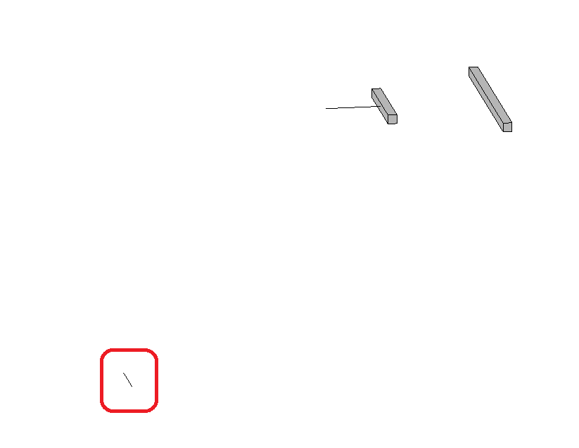
Question: I created two beams through different codes. Their FamilySymbols are the same. But their left faces' (marked as red in pic) normal are different!
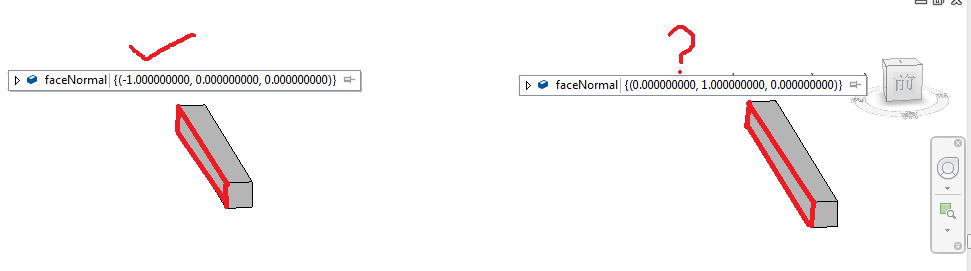
The face normal of the left beam is the same as I expected, (-1,0,0).
The face normal of the right beam is wrong and I don't know why.
Attached is my project for your reference.
Working Plane has no Effect
Answer: It seems that one beam is bound to a working plane, and the other one is unbound. Is this intended? This binding can influence the position of the FamilyInstance in WCS.
Response: Bounding to a working plane is not my intention. Both beams are created using this method:
  Instance = Doc.Create.NewFamilyInstance( line,
    FamilySymbol, Level, StructuralType.Beam)
How can I avoid bounding to a working plane when creating? Why and how would a working plane influence the FamilyInstance? If I can't change the way of creating the right beam, how can I get the correct face normal like the left beam? Thanks!
Answer: You can try passing null for Level. Unfortunately, it's not explicitly mentioned in the documentation, but the Level parameter is optional. The beam, after all, it is a family; like every family, it has a local coordinate system. If you bind it to a plane, then its LCS may no longer be identical to WCS; its local Z axis will correspond to the Z axis of the reference plane. What you are seeing is the beam's face normal in LCS; that's why they differ, even if they point in the same WCS direction.
Response: I passed null for Level and the right beam was bound to no working plane this time. But both beams' faces' normal are the same as previous.
Non-Picked Face Normals are Correct
Answer: The Revit API documentation RevitAPI.chm says this about the PlanarFace.FaceNormal property:
This property is the "face normal" vector, and thus should return a vector consistently pointing out of the solid that this face is a boundary for (if it is a part of a solid).
There is also another method, Face.ComputeNormal: It will always be oriented to point out of a solid that contains the face.
I downloaded your sample file and investigated the face normals. For each of the two Elements, there are six sides having FaceNormal values as expected, all pointing outwards. Could it be that you compare the faces by index, meaning the first face in the left element's face list is compared to the first face in the second one's face list? The geometry objects are not returned in order but randomized. As far as I can see, there is no problem at all.
Response: I understand your points and thank you. Below is my test code to calculate the face normal and snapshot of the result. I was not using index to get the face.
  Reference refFace = null;
  while( true )
  {
    try
    {
      refFace = sel.PickObject( ObjectType.Face,
        "select a face" );

      Element selectedElement = doc.GetElement(
        refFace );

      GeometryObject selectedGeoObject = selectedElement
        .GetGeometryObjectFromReference( refFace );

      Face selectedFace = selectedGeoObject as Face;
      PlanarFace selectedPlanarFace = selectedFace
        as PlanarFace;

      BoundingBoxUV box = selectedFace.GetBoundingBox();
      UV faceCenter = ( box.Max + box.Min ) / 2;

      XYZ computedFaceNormal = selectedFace
        .ComputeNormal( faceCenter ).Normalize();

      XYZ faceNormal = selectedPlanarFace.FaceNormal;

      MessageBox.Show(
        $"computedFaceNormal: {computedFaceNormal.ToString()}, "
        + "faceNormal: {faceNormal.ToString()}" );
    }
    catch( Autodesk.Revit.Exceptions.OperationCanceledException e )
    {
      return Result.Cancelled;
    }
  }
When you say, "there are six sides having FaceNormal values as expected", do you mean the left face's normal of the right beam is (-1,0,0)?
Answer: Yes. I just read the solid's faces via RevitLookup. For both of the elements, there were six PlanarFaces, each with perfect FaceNormal values. May it be that the selection function itself returns a false face? Seems to be the front face instead of the displayed lateral one.
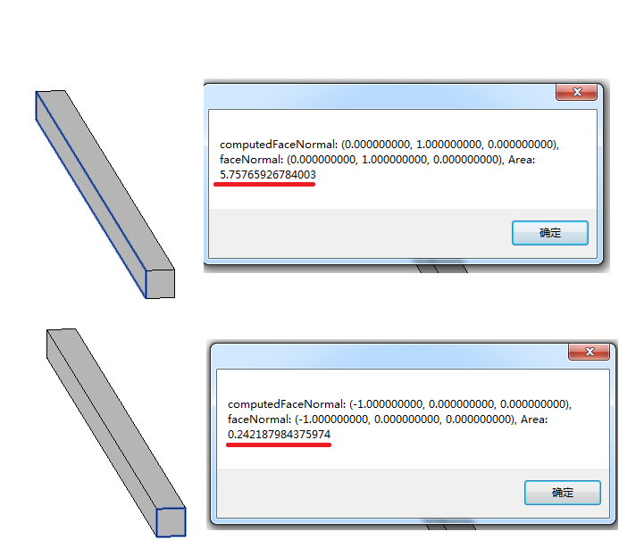
Response: I added this code to display the area:
  MessageBox.Show(
    $"computedFaceNormal: {computedFaceNormal.ToString()}, "
    + "faceNormal: {faceNormal.ToString()}, "
    + " Area: {selectedFace.Area.ToString()}" );
I tested it again. The area is correct, but the face normal is not.
Answer: When getting the solids and their faces, I draw the normals as ModelLines, starting at the faces' centre points:
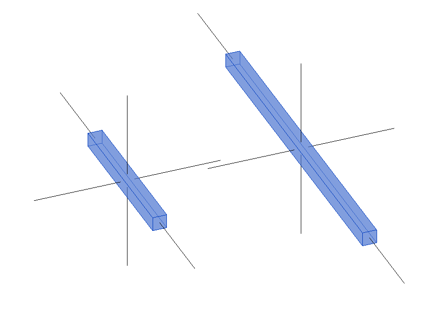
Everything looks correct, this way.
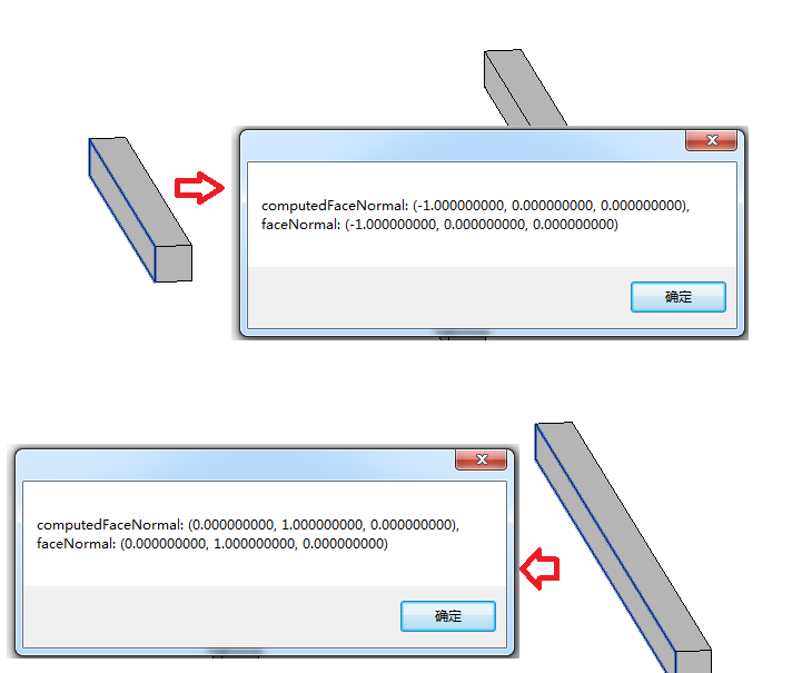
When I pick a face, I get this result with the left one:
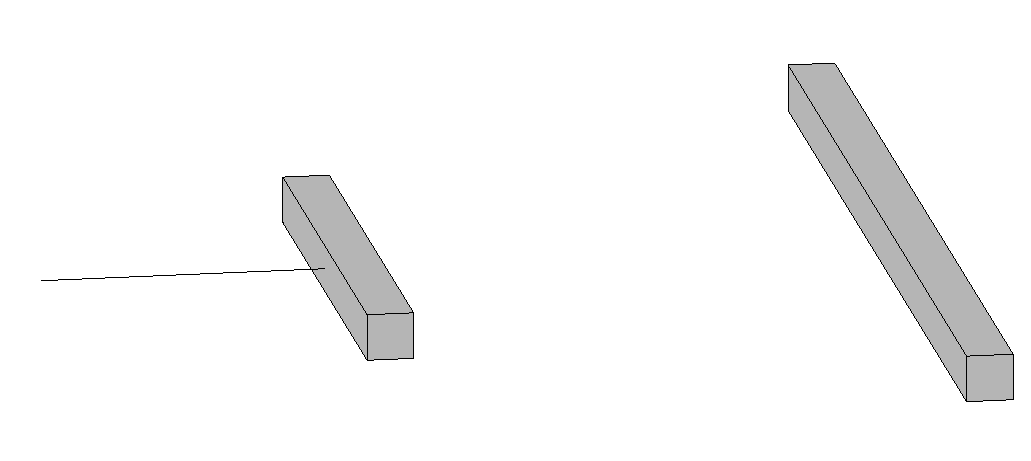
But I get this when picking the right one:
What does it mean ?
In fact, the face returned is not transformed to the project context.
The solid resides around the 0/0/0 project origin.
I've drawn the face boundaries, too:
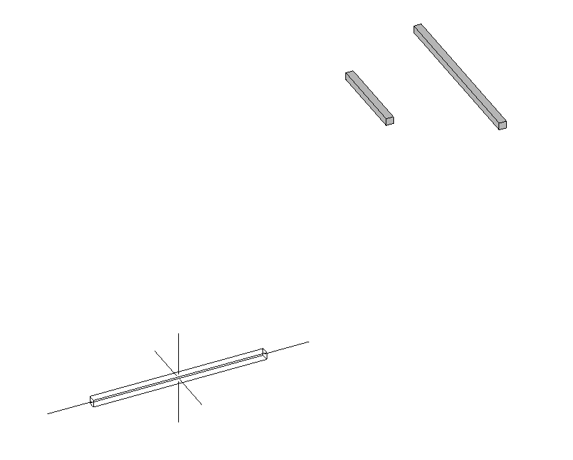
Strange. No idea.
Response: I did further investigation. I found that I've added coping on the left beam before picking it. So, when I add coping on the right one it works right! Why?
Solution – Detecting When to Use LCS versus WCS
Answer: Your comment on coping is the last piece of the puzzle.
When a family instance is
- cut,
- joined,
- coped
- and (apparently) has been copied
Revit has to calculate the solids of the instance "in situ" as it will be different from the solids from the family definition. So, the normal of the face will be relative to the project.
In all (??) other cases Revit treats the solids as "instances" of the solids from the family definition. And by some Revit-logic, when asked for Face.ComputeNormal, it gives the normal relative to the family. Quirkier still, it gives the Face.Origin in project coordinates.
So, with family instances that are not cut, joined or coped, you need to transform the faceNormal to project coordinates.
As you already have a reference to the face, you can easily test for this condition:
  refFace.ConvertToStableRepresentation( doc )
    .Contains( "INSTANCE" )
So, add this to your code:
  if( refFace.ConvertToStableRepresentation( doc )
    .Contains( "INSTANCE" ) )
  {
    Transform trans = ( selectedElement
      as FamilyInstance ).GetTransform();

    computedFaceNormal = trans.OfVector(
      computedFaceNormal );

    faceNormal = trans.OfVector( faceNormal );
  }
Response: Classic! Thank you all so much!
Ever so many thanks to Fair59 for coming to the rescue once again!
Retrieval of Picked Geometry Face from Instance is Untransformed
The discussion above also helps understand this old case on how to transform picked element face geometry to WCS:
Question: I am currently picking faces from geometry that is likely to be inside of a linked DWG file.
From the reference, I access the element geometry like this:
  Element e = Document.GetElement( reference );

  GeometryObject go
    = e.GetGeometryObjectFromReference( reference );
My problem is that the faces that are retrieved in this case are not transformed to the instance location.
Answer: I would imagine that if the element e is an instance, then:
- You can query it for its geometry.
- The geometry will contain a geometry instance.
- The transform is provided by the
GeometryInstance.Transformproperty.
Response: The problem is that I'm trying to select specific faces from within a DWG instance which has hundreds of faces.
So, while I can get all of the geometry from the element (transformed), I'm not sure if I can figure out which Reference or GeometryObject matches the selected face.
Answer: You can use the Instance.GetTransform method. That is at the element level.
Response: Yes, Instance.GetTransform would return the transform of the instance, but using that with the untransformed face from the pick would require me to transform everything that comes out of the face, such as normals, curvature, evaluated points, triangulation points, etc.
That sounds like a lot of work!
Answer: Unfortunately, I see other option for this. If you are interested in the edges and edge points, the curves can be transformed. The face itself cannot.