Wall and Opening Tessellation
Let's turn to a geometric question on tessellation, expanding on the discussion on TessellateSolidOrShell – holes versus wholes.
Question
I am exporting Revit wall geometry to an external application for comparison of net and gross wall areas.
I have a problem with the fact that Face.Triangulate(double levelOfDetail) creates a different tessellation segmentation of neighbouring faces for the wall and its opening, although the underlying intersection curve between them is obviously the same.
Why does the tessellation segmentation differ in this manner? The levelOfDetail in unchanged.
What can I do to get the same segmentation for the wall and its opening?
Here is an example image:
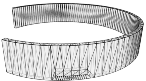
Note that the segmentations of the exported wall and opening solids differ:
I also tried to use the method TessellateSolidOrShell(Solid, SolidOrShellTessellationControls), but the result is similar and the segmentation of the exported wall and opening solids differs there too, cf. the discussion
on TessellateSolidOrShell – holes versus wholes.
Answer
Actually, the problem in this case is different.
I don’t think the user’s request is reasonable, for reasons I state below. The user wants to calculate wall areas (and other quantities) of a wall with and without openings: 'net' and 'gross' areas.
The Building Coder published a whole series of blog posts on that topic:
- Retrieving wall openings and sorting points
- Wall opening profiles
- Determining wall opening areas per room
- More on wall opening areas per room
- Two energy model types
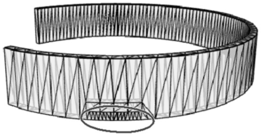
To calculate these areas, they subtract the wall with openings from the wall without openings to get solids representing the shapes of the openings. Their application requires faceted shapes, so they triangulate these various 3D shapes. The wall with an opening, triangulated looks like this:
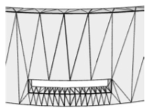
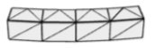
Here is the shape of the opening, triangulated:
The user says that they then merge the triangulated opening shape into the triangulated wall-with-opening shape to get the 'gross' wall without openings, in triangulated form, so that they can calculate the face areas for the 'gross' wall. Their merge operation requires the triangulations of the two objects to match, so it fails in this case because the triangulations of the opening shape’s faces differs from the triangulations of the corresponding faces of the wall-with-openings.
Unfortunately, the Revit triangulation process is not aimed at merging the resulting triangulated objects.
Therefore, there is no reason why Revit would make the triangulations of the faces of the opening match the triangulations of the corresponding faces of the opening shape.
For example, the triangulation of the bottom face of the opening must match the triangulation of the vertical face below it (on the side of the wall facing us). But the vertical face is the entire side face of the wall (facing us), and its triangulation depends on the overall shape of that face. By contrast, the vertical face that’s facing us on the opening shape has a different overall shape than the corresponding face on the wall, so it’s to be expected that it may get a different triangulation. The conditions on the bottom faces of the wall and the opening shape imposed by adjacent faces are therefore different in general, so one shouldn’t expect that the triangulations of those two faces will 'match', or that the triangulations of the side face of the opening shape that’s facing us will match the triangulation of the portion of the wall’s side face that lies below the opening.
In general, it seems that in order to avoid certain limitations in the user’s tools and algorithms, they want to impose conditions on Revit’s solid triangulation API that are not really reasonable.