WTA Mech and TTT for Provision for Voids
Today is the last day of the Forge accelerator, and I am still working on the ForgeFader project.
The topics today are mainly related to Revit, though:
- Google prettifier on GitHub
- WTA mechanical family placement add-in
- Provision for void
- What is a provision for void?
- Creating a provision for void
- Provision for void user interface
Google Prettifier on GitHub
I happened to notice yesterday that the Google JavaScript code prettifier moved and now lives in GitHub.
The script can now be loaded like this:
<script src="https://cdn.rawgit.com/google/code-prettify/master/loader/run_prettify.js"></script>
I use that to present JavaScript sample code here on the blog.
WTA Mechanical Family Placement Add-in
Allan @aksaks @akseidel Seidel made a number of contributions here in the past, including:
- Stacked Ribbon Button Panel Options
- FireP and 3d Aimer
- Ribbon panel implementation sample
- Fire protection related family placement tools
- 3d Aimer that "aims" a special Revit family instance at a target
- WTA Elec – another family plunk and concept share
Revit, Add-in, complex family placement using the plunk class
This sequence shows a complex placement of three family instances as handled by a "plunk" class intended to provide a universal placement handling.
His newest sample is presented in the Revit API discussion forum thread on an automation experiment, family placement, its tag and then a remote tag.
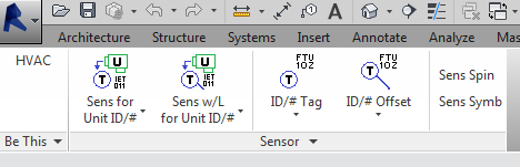
It provides a similar ribbon panel and tool collection for family instance placement and management for tasks primarily oriented towards the mechanical domain:
Apologizing for beginning to wear out a welcome, here is a video and code share for yet another custom ribbon specific task command involving family placement and tags. The ribbon panel split button control being used is a variant of what is mentioned in stacked ribbon button panel options.
One idea presented is a remote tag. Maybe this is commonly done in Revit practice. The remote tag here is simply a tag on item where the tag itself is placed in proximity to a different item that is a system client to the former item. What is really needed is for Revit tags to show values from an indexed object instead of the object the tag tags. Perhaps it does this. Anyway, that is part of what is seen in the video.
Other items of interest are "Host face normal direction used to drive symbology orientation" and "User settings for family names, types and tag parameter names". The first is a way used to orient based on which direction the host face faces. The idea could be used with a complex family that is capable of rotating within itself to produce a face based family placement that is "always level" so to speak. Only a crude family is used in the demonstration but the code behind does provide the necessary angle to "level". The second is an attempt to externalize family names, family types and parameter names outside of the hard coded add-in. The need is necessary for any type of task related ribbon customization where aspects to the task are not static.
Here is Allan's more detailed description from the GitHub repo:
Revit Add-in in C# — Creates a custom ribbon tab with discipline related tools. The tools at this writing are for placing specific Revit family types with some families requiring parameter settings made on the fly.
This repository is provided for sharing and learning purposes. Perhaps someone might provide improvements or education. Perhaps it will help to boost someone further up the steep learning curve needed to create Revit task add-ins. Hopefully it does not show too much of the wrong way.
The tools in this ribbon use classes that provide Revit family instance placement functionality with less overhead the standard Revit user interface. The classes are intended to provide a universal mechanism for placing some types of families, including tags. The custom tab employs menu methods not commonly explained, for example a split button sets a family placement mode that is exposed to the functions called by command picks. Other tools use add-in application settings as a way to persist settings or communicate to code that runs subsequently within a command that provides a task workflow.
This add-in demonstrates many of the typical tasks and implementation required for a family placement tab menu interface, e.g.:
- Creating a ribbon tab populated with some controls
- Tool tips
- Image file to button image
- Communication between controls and commands the controls execute
- Establishing the family type for placement
- Determine if the correct pairing exists in the current file
- Automatically discovering and loading the family if it does not exist in the current file but does exist somewhere starting from some set directory
- Providing the family type placement interface
- In multiple mode or one shot mode
- With a heads-up status/instruction interface form
- As WPF with independent behaviour
- Sending focus back to the Revit view
- Returning the family instance placement for further processing after the instance has been placed
- Managing an escape out from the process
- Handling correct view type context
- Changing family parameter values
Much of the code is by others. Its mangling and ignorant misuse is my ongoing doing. Much thanks to the professionals like Jeremy Tammik who provided the means directly or by mention one way or another for probably all the code needed.
Here are some aspects that may be of specific interest:
- Hybrid splitbutton behaviour — A splitbutton control with four buttons, where the top two execute one of two types of the same task and the bottom two invoke a settings panel for one of the corresponding task types. The top two buttons, being tasks the user is likely going to repeat, remain as the last button selected. The bottom two buttons are incidental tasks the user would not need to repeat nor want to be the splitbutton's face button. The splitbutton face button reverts back to what is was before the user selected one of the bottom two button. That is the hybrid behaviour. This idea was discussed here: thebuildingcoder – stacked-ribbon-button-panel-options
- Host face normal direction used to drive symbology orientation — The HVAC sensor family placed by the tools has two symbology orientations, because Revit does not really support a universal "view independent text". The family's symbology would be wrong 50% of the time it were placed. The code attempts to use the host face normal direction to more correctly pick which of the two orientations to make visible. Each orientation's visibility is controlled by a parameter. Only one parameter needs to be set, because the other parameter is function controlled in the family to be
not(the_other). - User settings for family names, types and tag parameter names — As a way to side step the problem of hard coding family names, types and tag parameter names, the user can set the names to some other values. Not implemented, but planned: an external file text to also house the standard settings.
- Remote equipment tag — Sensors, like thermostats, for example, are often the client to a piece of a mechanical system. The mechanical system name the sensor is a client for, an ID number for example, is typically placed next to the sensor on construction plans. That ID number is part of the mechanical equipment properties, but not the sensor properties, unless it is duplicated to the sensor. Therefore, tagging the sensor using the latter method involves more effort and maintenance. The remote equipment tag is a tag to the mechanical equipment placed at the sensor. That is what this add-in is doing. It would be nice if Revit were to support an indirect tag value, like the way a microprocessor does indirect addressing. Then the sensor could be tagged with a tag that gets its value from the parameter values of an indirectly addressed object.
- Multiple view annotation placement — This add-in can place the annotations, the tags, simultaneously in more than one view at a time. The final tag placement code iterates through a list of candidate views when placing the tag. That list is developed by a single function using specific rules, which one has to adapt to one's needs, operating on parent view names. For example, if the active view is a dependent view, its parent view name is used in the candidate logic. The reason for this feature is due to one of Revit's worst usability problems, where annotation is relegated to the output composition task and not visible during the more important design and engineering tasks.
Provision for Void
We discussed numerous examples of the temporary transaction trick in the past, the last one just last week, to obtain a section marker endpoint.
That and others are listed in The Building Coder topic group on handling transactions and transaction groups.
Here is another clever use to obtain provisions for void, last mentioned in the discussion
on using ReferenceIntersector in linked files.
Håvard Dagsvik of Symetri, who contributed to numerous discussions in the past, e.g., determining wall opening areas per room, brought up a new idea:
Just wanted to share with you something I came across the other day about ProvisionForVoids. Those are basically "proposals for openings that are to be coordinated between HVAC and architectural/structural design applications". We create those proposals as FamilyInstances.
What is a Provision for Void?
A ProvisionForVoid is a request/proposal for an opening in a structural element such as a wall or floor.
BuildingSmart published the #CV-2x3-157 agreement on a particular type of building element proxy to exchange provisions for voids saying, "Such 'proposals for openings' – or provisions for voids are 3D bodies that indicate the required void for building service flow segments. The voids are not yet subtractions of the building element (wall, slab), but placeholders, that have to be converted into "real" openings by the architect or structural designer."
So the request/proposal is a 3D body, a solid simulating a void. One request is one FamilyInstance. If the Structural Engineer approves the request he will create the actual void with the requested size.
It could be you are an architect with a Door in a structural wall. (That wall belongs to the structural engineer) Or you may be an MEP engineer with a CableTray passing through the wall. Both will need an opening.
Creating a Provision for Void
Getting the size of an opening cut for a door is not straight forward.
I implemented working code doing it that either is much too slow, using EditFamily,
or becomes too long, by analysing invisible lines obtained in the project file.
Then I realized if you set a door as demolished, Revit will automagically create the "provision" element. Revit creates an "infill" wall because the element got demolished.
So, by using some ideas shared by The Building Coder, I put together the following solution. In this case, it's about provisions. But it can be used with the "RoomSurfaceMaterial" code we did some time ago. This is tested somewhat large scale and works well, seems very reliable and fast :-) A bit similar to the temporary deletion trick you have mentioned. But this will get you the actual opening element.
  using( TransactionGroup transGroup
    = new TransactionGroup( doc ) )
  {
    transGroup.Start( "TempRollback" );

    // register the updater;

    doc.Application.DocumentChanged
      += new EventHandler<
        Autodesk.Revit.DB.Events
          .DocumentChangedEventArgs>(
            application_DocumentChanged );

    FamilyInstance door = null; // get the door here;

    using( Transaction t = new Transaction( doc ) )
    {
      t.Start( "name" );
      door.DemolishedPhaseId = door.CreatedPhaseId;
      t.Commit();
      // Revit has now created the "infill" element;
    }

    Wall provision = null;

    // "addedIds" contains the "infill" element;

    foreach( ElementId id in addedIds )
    {
      Element e = doc.GetElement( id ) as Element;
      if( e is Wall )
        provision = e as Wall;
    }

    if( provision != null )
    {
      // collect whatever info you need
      // about void geometry
    }

    // unregister the updater;

    doc.Application.DocumentChanged
      -= new EventHandler<
        Autodesk.Revit.DB.Events
          .DocumentChangedEventArgs>(
            application_DocumentChanged );

    transGroup.RollBack();
  }

  // the variable

  private static ICollection<ElementId> addedIds
  {
    get;
    set;
  }

  // pick up the "infill" element Revit just created
  // when we set the door as demolished

  private static void application_DocumentChanged(
    object sender,
    DocumentChangedEventArgs args )
  {
    addedIds = args.GetAddedElementIds();
  }
}
Here is a sample project. It demonstrates how to get the opening void for doors and windows as a solid using the temporary demolish trick.
There's also a second method in there that gets the curve framework of the void. Somewhat mysterious curves they are not visible in the project or the family. From those curves, it is possible to create a solid. That is what I ended up doing in my final application. (Or I might do a mix if the curve method fails).
However way you get that transient solid it can be used for a lot purposes. In this case, I was working on creating ProvisionsForVoids as FamilyInstances. So I use the size of the solid as size for each FamilyInstance.
These methods can also be used to improve the SpatialElementGeometryCalculator project described in Håvard's SpatialElementGeometryCalculator enhancement.
This add-in shows how you can obtain the opening size you need to request. In our final add-in we use the solids it creates as basis for size and rotation when creating FamilyInstances. It shows two different ways you can get that size/3D body for Doors/Windows. Without having to rely on how the family is made, or its parameters. Families can be made in an infinite number of different ways. Their visible geometry is hard to analyse with a consistent result. I needed a consistent way of getting that opening request correct in every case.
Hopefully what we have here can be of use to someone out there ;-)
Many thanks to Håvard for this advanced and well-tested yet simple solution to a very challenging task!
Provision for Void User Interface
An additional comment on the user interface...
I implemented a modeless environment with an exit button to interact with this functionality.
The UI looks like this:
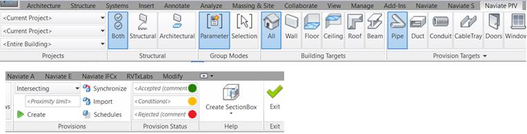
The ProvisionForVoid code above is launched from this UI when the user selects "Doors" or "Wall" and presses "Create".
And we are using this type of UI in several ways now; this is another example that writes Fire or Acoustic codes to elements:
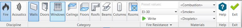
Both of them could have been done "the usual way" with a Windows Form.
This is just so much better, "modeless" but still inside a valid API context.
No need for OnIdling or external events here, a few others, but not those.