Adding Custom Geometry to the Forge Viewer
I am in Gothenburg supporting the Forge accelerator.
My project here is ForgeFader, implementing the same end user functionality as the RvtFader Revit C# .NET API add-in that I implemented last week.
I have not quite finished it yet, but the existing functionality looks as if it already ought to be very useful indeed to anyone working with geometry in the Forge viewer.
- Working in Visual Studio Code
- ForgeFader
- Implementation
- Adding custom geometry to the Forge Viewer
- Next steps
- Detailed notes and pointers
Working in Visual Studio Code
Inspired by Kean Walmsley's note on enabling Visual Studio Code’s integrated web debugging, I am using Visual Studio Code to develop ForgeFader and very happy with it indeed.
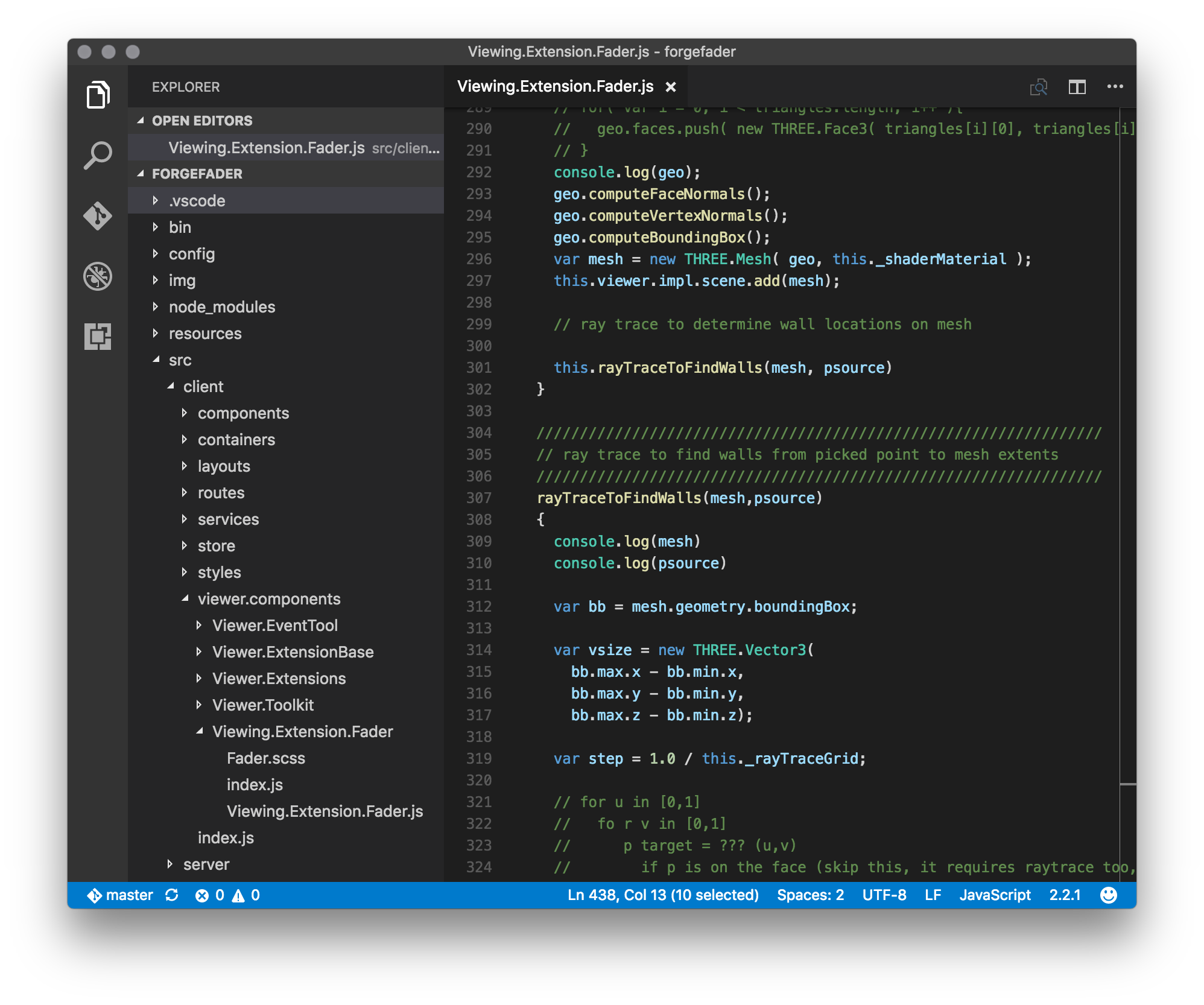
I have not actually enabled the integration with Chrome debugging that is the main point of Kean's article, but just using this as an editor is a good start.
ForgeFader
ForgeFader implements a Forge viewer extension to calculate and display signal attenuation caused by distance and obstacles in a building model with a floor plan containing walls.
It implements a functionality similar to RvtFader:
Given a source point, calculate the attenuation in a widening circle around it and display that as a heat map.
Two signal attenuation values in decibels are defined in the application settings:
- Attenuation per metre in air
- Attenuation by a wall
This app is based on Philippe Leefsma's Forge React boilerplate sample.
Please refer to that for more details on the underlying architecture and components used.
Implementation
The ForgeFader implementation lives in Viewing.Extension.Fader.js.
On loading, in onGeometryLoaded, it determines the Revit BIM wall fragments for subsequent ray tracing.
On picking a point on a floor in the model, in onSelection, it launches the attenuationCalculator function to do the work.
That fiddles around a bit to determine the picked floor top faces and add a new mesh to the model on which to draw the attenuation map.
Once the mesh has been added, it in turn calls rayTraceToFindWalls to create a bitmap representing the signal attenuation to be displayed by a custom shader.
Adding Custom Geometry to the Forge Viewer
When debugging any kind of geometrical programming task, it is of utmost importance to be able to comfortably visualise the situation.
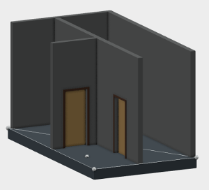
In this app, I add three different kinds of geometry dynamically to the model displayed by the Forge viewer:
- Points and lines representing the top face of the floor and the picked source point.
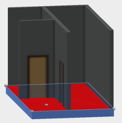
- A mesh representing the top face of the floor to be equipped with a custom shader and offset slightly above and away from the floor element surface.
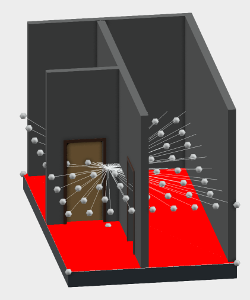
- Points and lines representing the raytracing rays.
Three example screen snapshots illustrate what I mean.
Display points and lines for debugging using drawVertex and drawLine:
Create a mesh to represent the floor top face and offset it up slightly above the floor surface:
A debug helper displaying lines in the model representing the ray tracing rays:
Next Steps
- Perform the raytracing to determine the number of walls between the picked signal source point and a grid of target points
- Generate a bitmap based on that information, or simply a mapping of
(u.v)values to the desired colour value. - Implement a custom fragment shader to display the (u,v) to colour mapping on the floor top face mesh.
Detailed Notes and Pointers
I made the following notes during the research and implementation steps.
- Colour gradient examples:
- A series of three consecutive approaches to solve the task, starting with the most obvious, for the learning curve. However, the last in the series, using shaders, although last in the learning curve, once understood, is actually probably the most effective and simplest approach.
- Projecting Dynamic Textures onto Flat Surfaces with Three.js.
- Using Shaders to Generate Dynamic Textures in the Viewer API.
- mourner/simpleheat, A super-tiny JavaScript library for drawing heatmaps with Canvas
- Setting up the new project based on boilerplate code:
- Fork forge-react-boiler.nodejs.
- Clone, npm install, npm start.
- Translate my Revit model to obtain a
urn: models.autodesk.io. - Load model into boilerplate: localhost:3000/viewer?urn=...
- My urn for the little house floor is
dXJuOm...ydnQ - localhost:3000/viewer?urn=dXJuOm...ydnQ
- Looked at
forge-rcdb.nodejssampleViewing.Extension.Configurator.Predix.jsonSelection; it relies onEventToolandEventsEmitter. - How to get the model object tree of 2d drawing.
Viewer.Toolkit/Viewer.Toolkit.jsgetLeafNodes.- For ray tracing, look at
library-javascript-viewer-extensionsViewing.Extension.Transform/Viewing.Tool.Rotate.jsonPointerDownandpointerToRaycaster. - Create a custom mesh with a finer resolution than the original face.
- Assign colours to the mesh.
- Call
scene.addand pass a mesh. - The viewer does not have any concept of the face of an element. It is all just individual triangular fragments.
- Philippe implemented a snapper tool to collect as many triangles as possible to guess what the face might be in his GeometrySelector in the library-javascript-viewer-extensions.
- Check out the function
drawFacein Snapper.js. - Shader produces all the points, calculates and sets result.
- Stemkoski Three.js Examples, Shader – Attributes (source).
- Intro to Pixel Shaders in Three.js.
I want to attach a fragment shader to the picked floor face. My shader should draw an image or texture directly, i.e., the desired 'heat map'. Here are som more complex pixel shader samples. I need to implement a fragment shader script and equip it with an id.
- WebGL shaders are written in GLSL, the OpenGL Shading Language.
- Pixel Shaders by Toby Schachman and the sample tutorial chapter.
- Philippe's first article on Forge viewer custom shaders.