Intersect Solid Filter, AVF vs DirectShape Debugging
We already discussed the important topics of the analysis visualisation framework AVF (category page), DirectShape (mesh import, new functionality), and the ElementIntersectsSolidFilter.
Today, let's look at a little-know restriction on the latter and how to work around it, raised and solved by Miroslav Schonauer, Solution Architect in Autodesk Consulting, and Scott Conover, Software Development Manager of the Revit API team:
- ElementIntersectsSolidFilter problem
- Resolution
- Rectangular prism solid construction
- DirectShape is easier than AVF for prototyping and visualisation
ElementIntersectsSolidFilter Problem
Question: I have a problem with the results of ElementIntersectsSolidFilter.
It is not behaving as I would assume.
I need to determine if a given point if within a tolerance, e.g., 100 mm, of any solid part of the wall and retrieve the list of such walls.
ElementIntersectsSolidFilter looked like an ideal solution:
- I create an
ElementIntersectsSolidFilter filterSphere =newElementIntersectsSolidFilter(tolSphere)with a Solid tolSphere of radius = tol. - Then, I use
new FilteredElementCollector( doc ).OfClass( typeof( Wall ) ).WherePasses( filterSphere );
Unfortunately, testing this with a given point that lies spot-on the wall face, I get NO walls for a tolerance of 100 mm, and the expected wall only for a tolerance of 1000 mm.
I suspected I was doing something wrong with my transforms, due to the complex workflow.
However, adding code to display the solid using AVF and the sphere creation code provided there prove that in both cases everything really is spot-on:
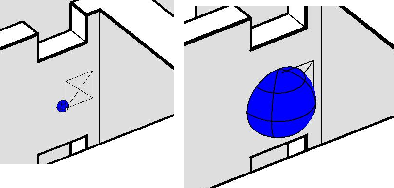
Finally, I worked out that I get the hit if I set the sphere tolerance greater than the wall thickness, e.g., 425 mm.
No hit is returned if it is less, e.g. 375 mm.
It looks as if the internal interpretation of this filter if really '3D intersection', i.e., the solid must fully 'go through' the element – in this case wall – geometry and not just 'penetrate' it, i.e. have a Boolean overlap.
Questions:
- Is this a bug or by design?
- If by design, what would be the best solution – is anything better or faster than checking for Boolean overlaps between the solids?
Resolution
Answer: This is indeed a limitation of the Boolean operations that sometimes crops up in Revit.
If neither joining entity intersects along an edge, the intersection is not properly detected. This is tracked as issue REVIT-32243.
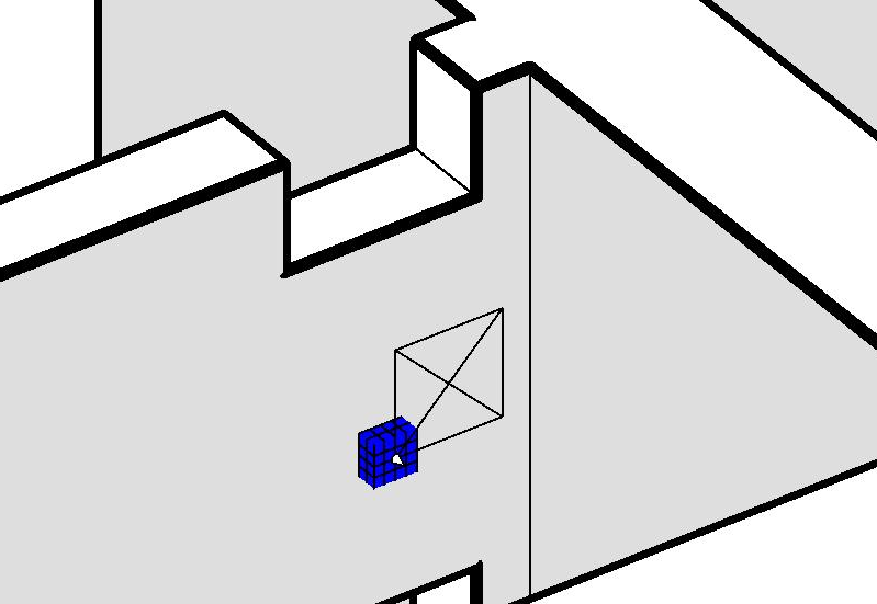
In your case, it would probably make sense to change from a sphere shape to a cube.
The cube should intersect the face on some of its edges and be reported correctly.
Response: Thank you for confirming what I’m sure is the root cause here!
It all adds up: with the smaller sphere, all the edges on the 'wall-surface meridian' are 100% ON the surface and do not really intersect it.
With the bigger sphere, the ones on the other end start intersecting the opposite surface.
It works fine even if I offset the centre point of the sphere by dXYZ=(1,1,1)[mm], since then the sphere edges intersect the closer surface.
I will switch to a cube and possibly add some pre-filtering based on the walls’ delta-expanded Bounding Boxes.
Rectangular Prism Solid Construction
Answer: Here is a quick cube or rectangular prism construction example:
  /// <summary>
  /// Create and return a cube of
  /// side length d at the origin.
  /// </summary>
  static Solid CreateCube( double d )
  {
    return CreateRectangularPrism(
      XYZ.Zero, d, d, d );
  }

  /// <summary>
  /// Create and return a rectangular prism of the
  /// given side lengths centered at the given point.
  /// </summary>
  static Solid CreateRectangularPrism(
    XYZ center,
    double d1,
    double d2,
    double d3 )
  {
    List<Curve> profile = new List<Curve>();
    XYZ profile00 = new XYZ( -d1 / 2, -d2 / 2, -d3 / 2 );
    XYZ profile01 = new XYZ( -d1 / 2, d2 / 2, -d3 / 2 );
    XYZ profile11 = new XYZ( d1 / 2, d2 / 2, -d3 / 2 );
    XYZ profile10 = new XYZ( d1 / 2, -d2 / 2, -d3 / 2 );

    profile.Add( Line.CreateBound( profile00, profile01 ) );
    profile.Add( Line.CreateBound( profile01, profile11 ) );
    profile.Add( Line.CreateBound( profile11, profile10 ) );
    profile.Add( Line.CreateBound( profile10, profile00 ) );

    CurveLoop curveLoop = CurveLoop.Create( profile );

    SolidOptions options = new SolidOptions(
      ElementId.InvalidElementId,
      ElementId.InvalidElementId );

    return GeometryCreationUtilities
      .CreateExtrusionGeometry(
        new CurveLoop[] { curveLoop },
        XYZ.BasisZ, d3, options );
  }
You will obviously want to pass in your own target location in the center argument.
Response: Thank you.
I confirm that the cube works fine as well!
To test this yourself, create a standalone hard-coded RVT model defining the geometry and an external command base don the code below, with the following:
- One wall in RVT.
- Code creates 3 solids: sphere with a radius < wall width, sphere with radius > wall width, cube with side < wall width, each with their centre *exactly* on one of wall side surfaces.
- Spheres created using the sphere creation for AVF and filtering code.
- For each solid, create the Intersect filter with wall; the first one should result in NO hits, the latter two OK.
- For visualization, use AVF to show the solids.
Besides the code above to create a rectangular prism, here is an analogous method creating a sphere:
  /// <summary>
  /// Create and return a solid sphere
  /// with a given radius and centre point.
  /// </summary>
  static public Solid CreateSphereAt(
    XYZ centre,
    double radius )
  {
    // Use the standard global coordinate system
    // as a frame, translated to the sphere centre.

    Frame frame = new Frame( centre, XYZ.BasisX,
      XYZ.BasisY, XYZ.BasisZ );

    // Create a vertical half-circle loop
    // that must be in the frame location.

    Arc arc = Arc.Create(
      centre - radius * XYZ.BasisZ,
      centre + radius * XYZ.BasisZ,
      centre + radius * XYZ.BasisX );

    Line line = Line.CreateBound(
      arc.GetEndPoint( 1 ),
      arc.GetEndPoint( 0 ) );

    CurveLoop halfCircle = new CurveLoop();
    halfCircle.Append( arc );
    halfCircle.Append( line );

    List<CurveLoop> loops = new List<CurveLoop>( 1 );
    loops.Add( halfCircle );

    return GeometryCreationUtilities
      .CreateRevolvedGeometry( frame, loops,
        0, 2 * Math.PI );
  }
I use the following to drive the AVF:
  private static int schemaId = -1;

  public static void PaintSolid(
    Document doc,
    Solid s,
    double value )
  {
    Application app = doc.Application;
    View view = doc.ActiveView;

    if( view.AnalysisDisplayStyleId
      == ElementId.InvalidElementId )
    {
      CreateAVFDisplayStyle( doc, view );
    }

    SpatialFieldManager sfm = SpatialFieldManager
      .GetSpatialFieldManager( view );

    if( null == sfm )
    {
      sfm = SpatialFieldManager
        .CreateSpatialFieldManager( view, 1 );
    }

    if( -1 != schemaId )
    {
      IList<int> results = sfm.GetRegisteredResults();
      if( !results.Contains( schemaId ) )
      {
        schemaId = -1;
      }
    }

    if( -1 == schemaId )
    {
      AnalysisResultSchema resultSchema1
        = new AnalysisResultSchema( "PaintedSolid",
          "Description" );

      schemaId = sfm.RegisterResult( resultSchema1 );
    }

    FaceArray faces = s.Faces;
    Transform trf = Transform.Identity;
    foreach( Face face in faces )
    {
      int idx = sfm.AddSpatialFieldPrimitive( face, trf );
      IList<UV> uvPts = new List<UV>();
      List<double> doubleList = new List<double>();
      IList<ValueAtPoint> valList = new List<ValueAtPoint>();
      BoundingBoxUV bb = face.GetBoundingBox();
      uvPts.Add( bb.Min );
      doubleList.Add( value );
      valList.Add( new ValueAtPoint( doubleList ) );

      FieldDomainPointsByUV pnts
        = new FieldDomainPointsByUV( uvPts );

      FieldValues vals = new FieldValues( valList );
      sfm.UpdateSpatialFieldPrimitive( idx, pnts,
        vals, schemaId );
    }
  }

  static void CreateAVFDisplayStyle(
    Document doc,
    View view )
  {
    using( Transaction t = new Transaction( doc ) )
    {
      t.Start( "Create AVF Style" );

      AnalysisDisplayColoredSurfaceSettings
        coloredSurfaceSettings = new
          AnalysisDisplayColoredSurfaceSettings();

      coloredSurfaceSettings.ShowGridLines = true;

      AnalysisDisplayColorSettings colorSettings
        = new AnalysisDisplayColorSettings();

      AnalysisDisplayLegendSettings legendSettings
        = new AnalysisDisplayLegendSettings();

      legendSettings.ShowLegend = false;

      AnalysisDisplayStyle analysisDisplayStyle
        = AnalysisDisplayStyle.CreateAnalysisDisplayStyle(
          doc, "Paint Solid", coloredSurfaceSettings,
          colorSettings, legendSettings );

      view.AnalysisDisplayStyleId = analysisDisplayStyle.Id;

      t.Commit();
    }
  }
DirectShape is Easier than AVF for Prototyping and Visualisation
Answer: Thank you for the confirmation and sample code.
One note regarding your use of AVF for visualisation and graphical debugging:
Nowadays, it is a lot easier to visualize 3D geometry by using DirectShape instead of AVF.
AVF still has its uses, but for prototyping and visualisation, DirectShape is a lot easier.
Response: So hard to keep up with all the great improvements for all products and APIs ;-)
DirectShape is on my list to try asap!
Many thanks to Miro and Scott for bringing up and solving this important issue!
I added the solid sphere and cube creation utility methods to The Building Coder samples in release 2016.0.120.3.