Setting up a 3D View like a Section View
Lots of add-in developers have struggled with various aspects of setting up cameras and views.
I summarised a number of them in two new topic groups:
- 5.37. Creating and Setting Up a 3D View
- 5.38. Creating and Setting Up a Section View
I keep hoping that they cover everything one needs to know in this area, together with Steve Mycynek's all-encompassing AU class CP3133 Using the Revit Schedule and View APIs.
Here is one recent example proving that this sometimes holds true, and yet finding the exact right approach for your particular case may require some research and effort on your side as well:
Question: I want to orient a 3D view like a section view.
Does the Revit API provide a ready-made function for this?
If not, how can I set the SectionBox of the 3D view to be like the section view?
I tried to set its Min, Max, and Transform properties, but the result is not the same.
Note: what I want to achieve is to set the section box of 3D view like the Revit 'Orient to view' command.
Answer: Thank you for your query.
I hope that the following two explanations by The Building Coder provide all you need:
If not, please provide a reproducible case for us to look at.
What follows now is a rather lengthy and all-to-typical repetition of where to look for answers, how to research the required settings and explore the results of the various settings ... you may want to simply skip right down to the solution...
Update 2014-8-20 10:47: Ok, thank you.
I provided the Revit File and Visual Studio project.
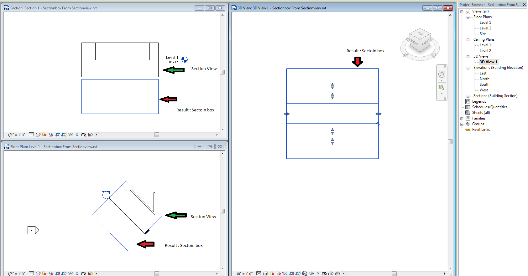
Steps: First I want to select the section view from Floor Plan view and run the add-in.
The add-in will create the 3D view and set its section box to be like the selected SectionView and then open this 3D view and the section view to check the result.
Expected result: when I pick the section box from 3D view to see its highlighted representation it has to be the same as the section view's on the floor plan and section view.
Observed result: the section box is shifted.
Update 2014-8-25 10:46: Can you please help? I did what you told me, describing the add-in steps and attaching the source code and Revit file. Thank you
Answer: Thank you for your update and image.
Unfortunately, I do not see the sample code or Revit file that you mention attached to the case.
All I see is your screen snapshot.
Did you follow the explanations by The Building Coder that I pointed out?
Did they not help resolve the issue?
What are your observations on that, please?
If that does not help, please try again to attach the required material in order for us to be able to reproduce and analyse the issue in more depth at our end.
Update 2014-8-25 11:07: Thank you, Jeremy. Before I asked you, I used The Building Coder, but this time I didn't find an answer to my question. I attached the files.
Answer: Thank you for your update and appreciation.
I see the sample code attached now.
I unpacked, installed and tested your sample add-in and can run and debug it successfully.
Apparently, it expects me to pre-select the section view symbol on level 1 before launching the command.
When I do so, it creates a new 3D view named '3D View 1'.
Now, what is your problem, please?
What is the difference between the observed behaviour and the results you would expect?
How can these differences be measured and visualised?
Update 2014-8-25 11:58: Thank you, Jeremy. The problem is that the section box of the created '3D View 1' is not the same as the section view, as you can see from the screen snapshot above.
Answer: I can indeed see certain differences in the PNG image.
However, in the real live 3D view, I cannot see anything similar.
How can I tell in the live 3D view whether the intended settings have been achieved?
How can I tell that they have not been achieved? :-)
For me, the way it currently appears looks totally all right. I assume that is not your intention, though :-)
Update 2014-8-25 13:18: Ok, perfect. First, you have to open three views:
- Floor plan of Level 1, defining the section view
- Created 3D view created by the add-in, "3D View 1"
- Section view "Section 1": select the section view on the floor plan and right click 'go to view'
Then select the section box of the 3D view "3D View 1".
You will see this section box highlighted in the two other views and can compare it with the section view boundary.
I hope you can understand me, and thank you again.
Update 2014-8-26 11:50: Dear Jeremy, can you update me if you understand me, or you need more explanation? Thank you
Answer: Yes, of course.
I believe I understand you perfectly well now.
You are creating a new 3D view using the View3D.CreateIsometric method, and would like to set up the newly created view's section box in a certain manner.
I published a number of articles on The Building Coder discussing this very issue.
For your and other's convenience, I now summarised them all as a new separate topic group on creating and setting up 3D views.
You have not yet explained to me in what way you have made use of the available information, and what is causing difficulties for you.
Please read the available information, explore how you can make use of it, and let me know the results.
So far, I am still pretty sure that all the information required is already published.
I will happily add your example to the blog once we resolve it, so do please let us continue working on this together.
One step forward might be to add some element, e.g. one single wall, to the sample project, making it easier to determine exactly how the 3D view is unintentionally offset from the desired location and how to improve it.
I used a similar technique when developing the code to define a section view exactly around a specific wall.
Maybe that exploration will help in this case as well.
This other approach might also be useful, where I explored how to set up a section view to match a given scope box and migrate it to Revit 2014.
Actually, come to think of it, I assembled another topic group for you as well, including these samples, on creating and setting up section views.
Please have a go at cracking this yourself and let us know how it goes.
I am sure you can succeed.
Update 2014-8-26 13:45: Thank you very much
I think there is a misunderstanding; the aim of this add-in is like you said, "to set up the newly created view's section box in a certain manner".
This manner is the section view and I use The Building Coder links that you sent me.
But the result is not the same; they have the same origin point, but differ at the UI "Section box, section view".
I wish I could make it easy for you to understand everything.
Update 2014-8-26 13:55: I think the discussion that you pointed to above is like what I need, but replacing the Scope Box by section view
Update 2014-8-27 11:58: Dear Jeremy, any good news?
Update 2014-8-27 19:25: Thank you, Jeremy, I did it, you can close the case.
Answer: Thank you for your updates.
Congratulations on solving this!
Would you like to share how you ended up doing it?
What steps did you take to research and discover the cause of the problem?
What was the problem in the end?
How did you resolve it?
Update 2014-8-28 18:59: Yes, sure.
Solution
First I was straightforward and set the bounding box of the section box like the bounding box of the section view using the Min, Max and Transformation properties.
The result was: Volume was right and the position was right but the Rotation or the direction was wrong; the Z and Y directions were swapped.
So I tried to replace them like the code I sent to you.
The result was: Volume was right, the position was wrong, the rotation or the direction was right.
Finally I found that the first was right but wrong direction, the second was right but wrong position so I realised that I have to get the common factor from the two approaches: the right position from the first method and the right direction from the second method.
Here is the final code:
  double yl = Math.Sqrt(BB.Min.Y * BB.Min.Y)
    + Math.Sqrt(BB.Max.Y * BB.Max.Y);

  double zl = Math.Sqrt(BB.Min.Z * BB.Min.Z)
    + Math.Sqrt(BB.Max.Z * BB.Max.Z);

  yl = yl / 2;
  zl = zl / 2;

  double YM = BB.Min.Y + (BB.Max.Y - BB.Min.Y)/2;
  double ZM = BB.Min.Z + (BB.Max.Z - BB.Min.Z)/2;

  NEWBB.Max = new XYZ(BB.Max.X, YM+zl, ZM+yl);
  NEWBB.Min = new XYZ(BB.Min.X, YM-zl, ZM-yl);
Conclusion
As said above, I hope that the available material covers all the typical needs for setting up views.
And finding the right approach for your particular case may require some research and effort on your side as well.