TessellateSolidOrShell – Holes Versus Wholes
Let's try to clarify further the various options to retrieve closed faceted shells from a Revit BIM.
When processed face by face, the Revit API will return gaps.
This issue was addressed by the introduction of the TessellateSolidOrShell method.
Let's look at some pros and cons of it, raised by the Revit API discussion forum thread on mapping the triangles it generates to faces.
We already looked at the topics of gaps in shells and the TessellateSolidOrShell method now and then in the past:
- Gaps in shells
- Face Tessellation
- Solid Centroid and Volume Calculation
- What's New in the Revit 2013 API > Small Enhancements & API Interface Changes > Geometry & sketching > Solid tessellation
Time for a recapitulation, I think, and a summary of the options at your disposal that I can see:
Question:
I'm trying to rewrite my old triangulation code where triangulation was done face by face. SolidUtils::TessellateSolidOrShell works really good, but I also need colour information, which I can't get from the Revit TriangulatedSolidOrShell method. I decided to map triangles manually by projecting triangle points on face (face.Project) and checking the distance. But this solution has few issues:
- It's slow. nFace * nTriangles complexity. For geometry with 100k and more triangles it could take a lot of time.
- Some triangles are not mapped at all.
- Some triangles are mapped to more that one face.
Is there some other way to triangulate or get colour information that I didn't find?
Answer: Yes, there is yes another possibility that you might want to consider. You could use a custom exporter. That will return all the triangles processed by the Revit graphics pipeline directly and include colour information.
Response: I tested this method, but looks like it also produces gaps between faces just like the face-by-face triangulation.
Answer: Oh dear, I am sorry to hear that.
The other option I can suggest is to fix up the holes yourself by matching vertices as they arrive, by ignoring any coordinate differences smaller than ca. 1 millimetre.
Simply implement a dictionary of all vertices encountered so far.
Each time you receive a new vertex, check whether it is close to another vertex already received. If so, use the one you already have instead of the new one received.
That should fix all the holes automatically.
I used that lots of times in various samples on The Building Coder blog, e.g. for the OBJ model exporter.
Response: I already do this. But on the border of two faces number of points doesn't match. For example imagine curved wall and border between top face and one of the sides. Side face after triangulation has one extra point on the top comparing to the top face. This leads to very thin missed triangle. Look at the following pictures.
On the first you see the wall after face-by-face triangulation:
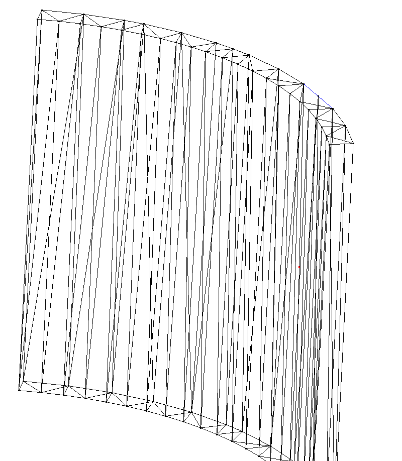
A missing triangle is marked with blue colour.
On the second picture I zoomed on the middle point of that triangle:
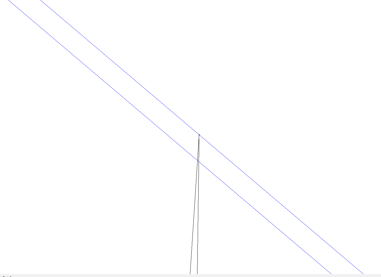
As you see, the top face lacks that point.
I think that there is no way to get gap-free triangulation without loosing material information. I'll try to somehow fix gaps on my side then.
Answer: Oh dear (again). Yes, indeed, I have heard about and discussed the problematic behaviour you describe in the past as well.
Revit triangulates each face as efficiently as required – and as roughly as possible – to display it.
The required precision will vary from face to face, obviously, causing the effect you describe.
This in turn causes problems for people interested in a closed shell, such as yourself.
This prompted the implementation of the TessellateSolidOrShell to solve the problem, which you already tried out.
Unfortunately, this method processes one body at a time and is less efficient than the other global processing methods.
Which takes us right back to square one.
I hope this clarifies the situation, at least.
Suggestion 1: develop a solution avoiding individual calls to TessellateSolidOrShell that tolerates these imprecisions, just like Revit's rendering pipeline and other workflows do.
Suggestion 2: implement a solution based on TessellateSolidOrShell to avoid these imprecisions and a workflow to drive it that is not time critical, e.g. overnight batch processing or something.
Response: Thanks for your help.
One more question about Faces. Is it possible that faces in single Solid have different Material? Maybe there is no need to map triangles after TessellateSolidOrShell to Faces.
Answer: Good question.
Unfortunately, I believe that is perfectly possible.
To test, I would suggest using the Revit user interface paint tool to colour different parts of a single wall.
Please let us know what you find out.