Explicitly Placing Rolling Offset Elbow Fittings
I continue the work on my MEP CASE BIM Hackathon project to calculate a rolling offset between two pipes, insert the rolling offset pipe segment and connect it to its neighbours.
The last missing puzzle piece was inserting appropriate fittings between the three pipe segments.
It only took me about a hundred debugging and testing iterations to nail down a working sequence to perform all the required steps manually, edging forward minute step by minute step.
Here are some of the main ones I encountered, researched and resolved for this post – hacking my thorny way towards the Revit veni, vidi, vinci:
- Create appropriate pipes and elbow fittings manually to determine what family symbol to use.
- Explore the family instance parameters to determine which ones to use to define its diameter and elbow angle.
- Place the elbow fitting instance.
- Rotate it around the pipe axis to point it in the proper direction toward the other, parallel, offset pipe.
- Shorten the original pipes to accommodate the additional distance between the elbow insertion and connection points.
- Place the rolling offset pipe segment between the elbow fittings.
- Create all connections between neighbouring pipes and fittings.
After implementing this and preparing the discussion below, Tate posted an extremely apt and helpful suggestion in a comment on connecting the rolling offset pipe to its neighbours:
The Document.NewElbowFitting will create, place and connect the fitting automatically for you, provided the two connectors are close enough.
This saves completing all these steps yourself and explicitly calling Connector.ConnectTo.
Many thanks to Tate for that!
Consequently, the entire discussion below can be seen as a possibly interesting and completely useless exercise.
I hope you enjoy it anyway, and find lots of use in the additional background understanding it provides.
Rolling Offset Geometry
Lets review the main geometrical points, based on the original pipes and the calculation of the distance required to accommodate the rolling offset between them at a specific given angle, in our case 45 degrees:
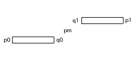
The points p0 and p1 are the two endpoints of the original pipes that are furthest apart. They remain unchanged.
The point pm is the midpoint between p0 and p1. This is used to define the centre point of the entire calculation and the resulting rolling offset pipe segment.
The points q0 and q1 are the two resulting corner points of the rolling offset. The original pipes closer two endpoints were adjusted back to these points when drawing a model line to represent the rolling offset, and also when inserting a pipe without any fittings.
They also become the insertion points for the elbow fittings. With fittings, the original pipes need to be cut back a bit further still to accommodate the additional distance between the fitting insertion and connection points.
Besides these main points, we need to be aware of the variable z storing the normal vector of the plane defined by the two parallel and offset pipes, which is also the plane hosting the rolling offset, since this is needed to calculate the angle to rotate the fitting around the pipe axis to point it exactly toward the other pipe.
Rolling Offset Fitting Placement
I implemented a new Boolean switch _place_fittings to toggle back and forth between the fitting placement and the previous rolling offset implementation variations.
The calculation of the rolling offset itself remains completely unchanged from the preceding versions.
The new version is currently implemented in a rather long spaghetti style code:
  FamilySymbol symbol
    = new FilteredElementCollector( doc )
      .OfClass( typeof( FamilySymbol ) )
      .OfCategory( BuiltInCategory.OST_PipeFitting )
      .Cast<FamilySymbol>()
      .Where<FamilySymbol>( e
        => e.Family.Name.Contains( "Elbow - Generic" ) )
      .FirstOrDefault<FamilySymbol>();

  // Set up first 45 degree elbow fitting

  FamilyInstance fitting0 = doc.Create
    .NewFamilyInstance( q0, symbol,
      StructuralType.NonStructural );

  fitting0.get_Parameter( "Angle" ).Set(
    45.0 * Math.PI / 180.0 );

  //fitting0.get_Parameter( bipDiameter ) // does not exist
  //  .Set( diameter );

  fitting0.get_Parameter( "Nominal Radius" )
    .Set( 0.5 * diameter );

  Line axis = Line.CreateBound( p0, q0 );
  angle = z.AngleTo( XYZ.BasisZ );

  ElementTransformUtils.RotateElement(
    doc, fitting0.Id, axis, Math.PI - angle );

  Connector con0 = Util.GetConnectorClosestTo(
    fitting0, p0 );

  // Trim or extend existing pipe

  ( pipes[0].Location as LocationCurve ).Curve
    = Line.CreateBound( p0, con0.Origin );

  // Connect pipe to fitting

  Util.Connect( con0.Origin, pipe, fitting0 );

  // Set up second 45 degree elbow fitting

  FamilyInstance fitting1 = doc.Create
    .NewFamilyInstance( q1, symbol,
      StructuralType.NonStructural );

  fitting1.get_Parameter( "Angle" ).Set(
    45.0 * Math.PI / 180.0 );

  fitting1.get_Parameter( "Nominal Radius" )
    .Set( 0.5 * diameter );

  axis = Line.CreateBound(
    q1, q1 + XYZ.BasisZ );

  ElementTransformUtils.RotateElement(
    doc, fitting1.Id, axis, Math.PI );

  axis = Line.CreateBound( q1, p1 );

  ElementTransformUtils.RotateElement(
    doc, fitting1.Id, axis, Math.PI - angle );

  Connector con1 = Util.GetConnectorClosestTo(
    fitting1, p1 );

  ( pipes[1].Location as LocationCurve ).Curve
    = Line.CreateBound( con1.Origin, p1 );

  Util.Connect( con1.Origin, fitting1, pipes[1] );

  con0 = Util.GetConnectorClosestTo(
    fitting0, pm );

  con1 = Util.GetConnectorClosestTo(
    fitting1, pm );

  // Connecting one fitting to the other does
  // not insert a pipe in between. If the
  // system is edited later, however, the two
  // fittings snap together.
  //
  //con0.ConnectTo( con1 );

  // Create rolling offset pipe segment

  pipe = doc.Create.NewPipe( con0.Origin,
    con1.Origin, pipe_type_standard );

  pipe.get_Parameter( bipDiameter )
    .Set( diameter );

  // Connect rolling offset pipe segment
  // with elbow fittings at each end

  Util.Connect( con0.Origin, fitting0, pipe );
  Util.Connect( con1.Origin, pipe, fitting1 );
Note that some of the calculations are more hard-coded than I would like.
Possibly a more optimal solution would base the calculations on the connector transform properties.
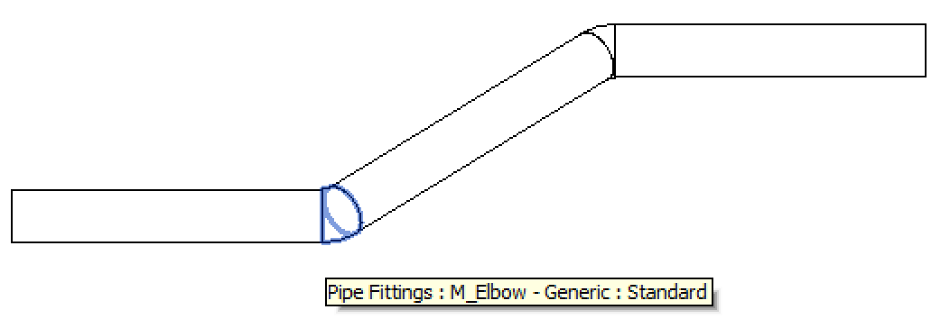
Resulting Rolling Offset with Fittings
Running this form of the CmdRollingOffset command in my sample model generates, places and connects the following fittings:
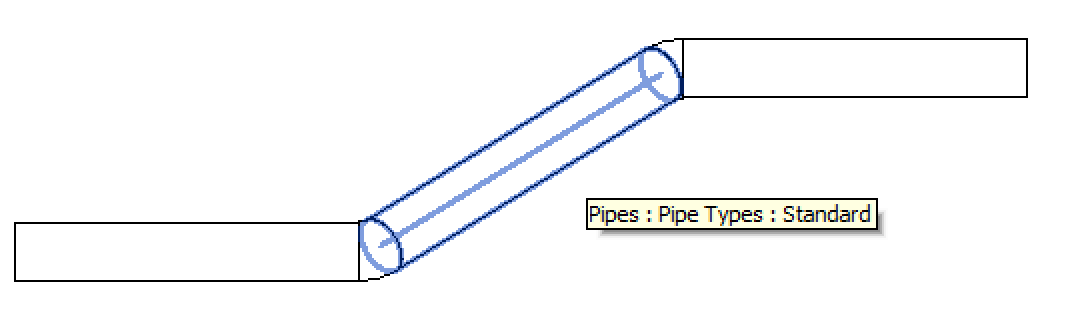
You get a good idea of the slantedness in all directions by looking at the end cross section of the rolling offset pipe segment:
Download
The code to place the elbow fittings and properly connect the rolling offset is included in the The Building Coder samples GitHub repository, in the external command CmdRollingOffset, and the version discussed here is release 2014.0.106.4.
As pointed out by Tate, a much simpler and more general solution is possible by calling the NewElbowFitting method to perform all of the steps listed above fully automatically, with the additional advantage of taking all the Revit pipe routing preferences and other settings into account.
Consequently, please stay tuned for the next instalment, coming up soon.