Create FaceWall on Slanted Mass Face
Happy New Year!
I hope you had a wonderful break and a good start into the New Year.
I spent New Year's Eve with my sons and some friends in a Swiss mountain village. We had a nice hike up and snowboard ride down the neighbouring hill with the Wildhorn in the background:

Now back to work and the Revit API. Here is a question that came up just before Christmas:
Question: I'm trying to create a wall by face on a slanted conceptual mass face. Do you have any example code showing how this might work?
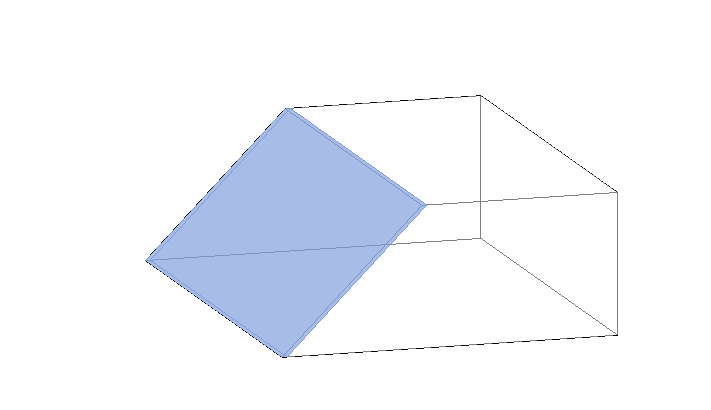
Answer: Here is a simple method that can be run in a project containing one single conceptual mass family instance. It searches the mass for a slanted face whose normal is (-1, 0, 1) and creates a FaceWall instance on that with no problem:
void CreateFaceWall( Document doc )
{
  FilteredElementCollector collector
    = new FilteredElementCollector( doc );

  FamilyInstance fi = collector
    .OfClass( typeof( FamilyInstance ) )
    .FirstElement() as FamilyInstance;

  XYZ nnorm = new XYZ( -1, 0, 1 ).Normalize();

  if( fi != null )
  {
    Options op = new Options();
    op.IncludeNonVisibleObjects = true;
    //op.DetailLevel = DetailLevels.Undefined;
    op.ComputeReferences = true;

    GeometryElement ge = fi.get_Geometry( op );

    if( ge != null )
    {
      foreach( GeometryObject obj in ge )
      {
        Solid solid = obj as Solid;

        if( solid != null && solid.Faces.Size > 0 )
        {
          foreach( Face f in solid.Faces )
          {
            PlanarFace pf = f as PlanarFace;
            if( pf != null )
            {
              XYZ fnorm = pf.Normal.Normalize();

              if( fnorm.IsAlmostEqualTo( nnorm ) )
              {
                string log = "";
                bool done = false;
                foreach( WallType t in doc.WallTypes )
                {
                  if( t != null )
                  {
                    ElementId id = t.Id;
                    using( Transaction trans
                      = new Transaction( doc ) )
                    {
                      trans.Start( "Add wall" );
                      try
                      {
                        FaceWall fw = FaceWall
                          .Create( doc, id,
                            WallLocationLine.CoreExterior,
                            f.Reference );

                        if( fw != null )
                        {
                          TaskDialog.Show(
                            "Succeeded",
                            "Succeeded" );

                          done = true;
                        }
                      }
                      catch( Exception ex )
                      {
                        log += t.Name + ": "
                          + ex.Message + "\r\n";
                      }
                      trans.Commit();
                    }
                    if( done )
                      break;
                  }
                }
                TaskDialog.Show( "Failed", log );
              }
            }
          }
        }
      }
    }
  }
}
Here is the resulting wall:

Inaccessible Location Property
Question: I tried to access the Location property of a FaceWall object.
However, nothing I tried leads to any useful result. In the following code snippet, both theCurve and thePoint remain null:
  Reference r1 = doc.Selection.PickObject(
    ObjectType.Element, "Please pick a wall: " );

  Element e1 = doc.GetElement( r1 );

  FaceWall faceWall = e1 as FaceWall;

  LocationCurve theCurve = faceWall.Location
    as LocationCurve;

  LocationPoint thePoint = faceWall.Location
    as LocationPoint;
Answer: Whenever a Revit element location is more complex than a simple point or curve, its Location property will contain more complex internal data (or possibly nothing at all) that currently cannot be represented by the Revit API.
In the case of a FaceWall, it is obvious that no simple point or curve would accurately represent the wall location.
In such cases, another option to determine a location for this kind of object is to analyse its geometry and use the information that provides.
Autodesk OrgOrgChart
For something completely different, here is an interesting graphical representation of the organisational changes Autodesk has been through in the last couple of years.
The OrgOrgChart (Organic Organization Chart) project looks at the evolution of a company structure over time. A snapshot of the Autodesk organizational hierarchy was taken each day between May 2007 and June 2011:
This representation is reminiscent of the Disk Tree visualization technique developed at Xerox Parc (Chi E.H., S.K. Card, 1999, Sensemaking of Evolving Web Sites Using Visualization Spreadsheets, Proceedings of the Symposium on Information Visualization (InfoVis '99), pp. 18-25), showing implicit and explicit affinities among information items and revealing relationships that are difficult to discover in traditional representations. Proximity or connections between items can reveal complex relationships in a comprehensive way, provide visual access to data structures, and enable detection of tendencies or patterns in the process.