Parts, Assemblies, PartUtils and DivideParts
Let's end this eventful week with another big and imporant topic that we've neglected for much too long.
So far, I presented just one single example of using the PartUtils class, and other information provided on it by a Google search is also awfully scarce.
Piotr Zurek of CADPRO Systems Ltd improved the situation by raising and promptly answering the following question:
Question: I wonder whether you have any sample code showing how to use the PartUtils.DivideParts method.
I'm trying hard to work it out but the documentation is pretty scarce on the topic.
Answer: I published a sample of using the PartUtils class demonstrating how to retrieve detailed wall layer geometry.
It exercises the CreateParts method, however, and not DivideParts, unfortunately.
Response: Seems like I cracked it. Attached a small working example. I'm just starting to play with the geometry related parts of the API, so this example is probably a bit clumsy :-)
Answer: I cleaned up your code a bit and tested it on the following simple wall:
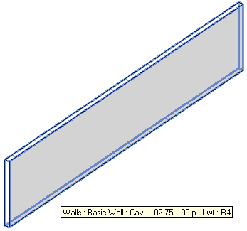
I simply run your sample command 'Divide Parts' and select the wall. I then display parts instead of original elements by setting the 'Parts Visibility' view property to 'Show Parts', et voila:
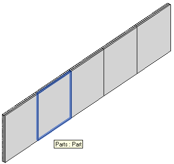
The wall is split into parts two ways, both by the CreateParts method, which separates the individual layers of the compound structure, and by DivideParts, which cuts each layer into divisions using the specified cutting curves or planes:
I also appended the handout document from Harry Mattison and Enrique Galicia's class CP5211 – Construction Modelling and API for Builders at Autodesk University 2011, which explains the usage a bit more and is reproduced in full below.
Response: Yes, that really provides a nice explanation of the whole topic.
I fixed some issues that you pointed out, and here is some further explanation:
For every division point I create a line, collinear with the wall going from a point 2 wall width in front of the division point to 2 wall widths after the division point.
Then I rotate those lines by 90 degrees to create curves perpendicular to the wall – those curves will be used to define the cutting lines (if I understand correctly).
Then based on endpoints of those curves I define reference planes used to divide the wall. Through my tests I have determined that it is not enough if the intersection curve is just 2*wall width.
It must have something to do with going beyond the extents of the dashed outline visible during manual editing of the division sketch. I don't know exactly what it has to be but 4*wall width works fine – the dashed outline seems to be just a bit more than twice the wall width.
This seems to work, but that was just trial and error.
Initially, I couldn't see my parts after the command completed. That was easily solved by setting the parts visibility in the view by adding:
  doc.ActiveView.PartsVisibility
    = PartsVisibility.ShowPartsOnly;
My impression is that I have to use calls to both CreateParts and DivideParts for this to work, just like in the user interface: first you click 'Create Parts', then the 'Divide Parts' button is enabled. If I don't call CreateParts first, the call to PartUtils.ArePartsValidForDivide returns false.
Initially, I was using two lists of 'cutting definitions', providing intersectingReferenceIds and the curveArray. Harry's AU materials make it clear that one of these can be empty. This very important detail is never mentioned anywhere in the API docs. Understanding that allowed me to clean up the code and get rid of all the lines having to do with reference planes that I was initially using.
Answer: Great job! I cleaned it up yet a little bit more, e.g. by adding an exception handler in case the user cancels the wall selection. I moved the selection and type checking out of the transaction and reordered the later statements.
I modified the definition of the wall width vector. It initially confused me that its direction followed the wall length instead of the width, and that you re-rotated it each time you translated it.
I simplified the geometrical manipulations a bit and changed the wall width vector to be perpendicular to the wall right from the start. The curveArray definition is significantly simplified, and I hope the geometrical manipulation is self-explanatory now.
Here is the final version of Piotr's 'Divide Parts' external command Execute method implementation:
  try
  {
    if( null == commandData )
    {
      throw new ArgumentNullException( "commandData" );
    }

    UIApplication uiapp = commandData.Application;
    Application app = uiapp.Application;
    UIDocument uidoc = uiapp.ActiveUIDocument;
    Document doc = uidoc.Document;

    Reference r = null;

    try
    {
      r = uidoc.Selection.PickObject(
        ObjectType.Element,
        new WallSelectionFilter(),
        "Select a wall to split into panels" );
    }
    catch( Autodesk.Revit.Exceptions
      .OperationCanceledException )
    {
      return Result.Cancelled;
    }

    Wall wall = ( r == null || r.ElementId
        == ElementId.InvalidElementId )
      ? null
      : doc.GetElement( r.ElementId ) as Wall;

    if( wall == null )
    {
      message = "Unable to retrieve wall.";
      return Result.Failed;
    }

    LocationCurve location
      = wall.Location as LocationCurve;

    if( null == location )
    {
      message = "Unable to retrieve wall location curve.";
      return Result.Failed;
    }

    Line line = location.Curve as Line;

    if( null == location )
    {
      message = "Unable to retrieve wall location line.";
      return Result.Failed;
    }

    using( Transaction transaction = new Transaction( doc ) )
    {
      transaction.Start( "Building panels" );

      IList<ElementId> wallList = new List<ElementId>( 1 );

      wallList.Add( r.ElementId );

      if( PartUtils.AreElementsValidForCreateParts(
        doc, wallList ) )
      {
        PartUtils.CreateParts( doc, wallList );

        doc.Regenerate();

        ICollection<ElementId> parts
          = PartUtils.GetAssociatedParts(
            doc, wall.Id, false, false );

        if( PartUtils.ArePartsValidForDivide(
          doc, parts ) )
        {
          int divisions = 5;

          XYZ origin = line.Origin;

          XYZ delta = line.Direction.Multiply(
            line.Length / divisions );

          Transform shiftDelta
            = Transform.get_Translation( delta );

          // Construct a 90 degree rotation in the
          // XY plane around the line start point

          Transform rotation = Transform.get_Rotation(
            origin, XYZ.BasisZ, 0.5 * Math.PI );

          // A vector perpendicular to the wall with
          // length equal to twice the wall witdh

          XYZ wallWidthVector = rotation.OfVector(
            line.Direction.Multiply( 2 * wall.Width ) );

          Curve intersectionLine
            = app.Create.NewLineBound( // Line.CreateBound
              origin + wallWidthVector,
              origin - wallWidthVector );

          IList<Curve> curveArray = new List<Curve>();

          for( int i = 1; i < divisions; ++i )
          {
            intersectionLine = intersectionLine
              .get_Transformed( shiftDelta );

            curveArray.Add( intersectionLine );
          }

          SketchPlane divisionSketchPlane
            = doc.Create.NewSketchPlane(
              app.Create.NewPlane(
                XYZ.BasisZ, line.Origin ) );

          // An empty list of intersecting ElementIds

          IList<ElementId> intersectionElementIds
            = new List<ElementId>();

          PartUtils.DivideParts( doc, parts,
            intersectionElementIds, curveArray,
            divisionSketchPlane.Id );
        }
        doc.ActiveView.PartsVisibility
          = PartsVisibility.ShowPartsOnly;
      }
      transaction.Commit();
    }
    return Result.Succeeded;
  }
  catch( Exception e )
  {
    message = e.Message;
    return Result.Failed;
  }
Here is DivideParts.zip containing the source code, Visual Studio solution and add-in manifest of the 'Divide Parts' command. For completeness' sake, I also added the source code from Harry's AU presentation below to it.
Many thanks to Piotr for this exploration and sharing the result!
Revit Construction Modelling and API for Builders
As mentioned above, while exploring this issue for Piotr, I also came across Harry Mattison and Enrique Galicia's class CP5211 – Construction Modelling and API for Builders at Autodesk University 2011. It was mentioned in the overview of Revit and AEC API Classes at AU 2011, and unfortunately I never had a chance to participate live in that class myself.
It discusses applying Revit construction modelling functionality creating parts, assemblies and assembly views.
It provides sample code exercising some PartUtils methods such as CreateParts, GetAssociatedParts, DivideParts, the PartMaker class, offsetting individual sub-parts, creating assembly instances and assembly views.
It also demonstrates using the VIEW_PARTS_VISIBILITY built-in parameter to programmatically set the part visibility in the view. Piotr shows a more modern and comfortable way to achieve that in Revit 2013, though, using the PartsVisibility property instead.
All in all, a nice complement to the sample presented above.
For your convenience and effective web searches, here is the full content of the AU handout document.
Please note that I have not reformatted Harry's original source code, so the lines are sometimes rather long and truncated in the blog post view. To see them in full, you can either copy and paste them to a text editor, open the original handout document provided below, or download the DivideParts source code provided above.
Introduction
Revit contains a wide variety of functionality that can be useful throughout the construction process. Scheduling, estimating, and coordination are a few of these areas, and there are many opportunities to use the Revit API to automate tasks related to construction modelling. The Revit API can help you perform construction modelling faster and more accurately.
Applying Revit Construction Modelling Functionality
This handout focuses on the new Construction Modelling features in Revit 2012 that support workflows for improved 4D sequencing, cost estimating, quantification, and other construction-related tasks by allowing you to create parts, assemblies, and assembly views in your Revit model.
Parts
Parts are dividing elements that can be created in Revit hosts such as walls, ceilings, floor slabs, and roofs. Dividing one of these elements creates new elements called parts which are associated with the element used to create them. This parent element is not deleted or altered by the creation of the parts – the parent continues to exist and can be edited after parts have been created from it.
The importance of parts is that they allow your Revit model to reflect the difference between how objects are designed and how they are constructed. For example, a large floor slab may be modeled as a single floor element in Revit, but it may not be constructed as a single element at a single time during the construction schedule. By dividing the single floor into multiple parts, the model can better reflect the realities of the construction process and more construction data can be captured.
Parts can be divided into sub-parts using the UI or API by specifying curves that define the division or by providing a set of intersecting references such as levels, reference planes, or grids. Curves that divide parts can be created with either closed loops or open loops that intersect the boundaries of the parent element. These parts will allow you to improve the design intelligence in your Revit model so that it can be used to produce more granular and accurate schedules, quantity takeoffs, and graphical views of the model.
After parts are created and divided, many different attributes of these parts can be modified to accurately indicate how the building will be built. For example, the material of a part created from a floor slab may have a different material than the remainder of the slab.
After creating parts, part list schedules can be created to more accurately track cost estimation and quantification data in the BIM model.
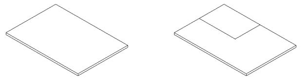
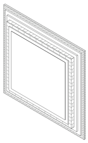
This example shows the situation before and after parts are created and divided by the following code:
  Autodesk.Revit.ApplicationServices.Application app = commandData.Application.Application;
  Document doc = commandData.Application.ActiveUIDocument.Document;
  UIDocument uidoc = commandData.Application.ActiveUIDocument;

  IList<ElementId> idList = new List<ElementId>();

  // Select an element to use for part creation. Can be a host element (floor, roof, etc) or a part created from one of these elements.
  Element pickedElement = doc.GetElement( uidoc.Selection.PickObject( ObjectType.Element ) );
  idList.Add( pickedElement.Id );

  // Determine which elements to divide.
  ICollection<ElementId> elementIdsToDivide = new List<ElementId>();
  if( PartUtils.AreElementsValidForCreateParts( doc, idList ) )
  {
    // AreElementsValidForCreateParts returned true, so the selected element is not a part but it is an element that can be used to create a part.
    Transaction createPartTransaction = new Transaction( doc, "Create Part" );
    createPartTransaction.Start();
    PartUtils.CreateParts( doc, idList ); // create the parts
    createPartTransaction.Commit();

    elementIdsToDivide = PartUtils.GetAssociatedParts( doc, pickedElement.Id, true, true ); // get the id of the newly created part
  }
  else if( pickedElement is Part )
  {
    // The selected element is a part, so that part will be divided.
    elementIdsToDivide.Add( pickedElement.Id );
  }

  // Create geometry that will be used to divide the part. For this example, a new part will be divided from the main part that is one quarter of the face. More complex intelligence could be coded to divide the part based on construction logistics or the properties of the materials being used to create the part.
  XYZ pointRight = null;
  XYZ pointTop = null;
  XYZ pointCorner = null;
  XYZ pointCenter = null;

  SketchPlane sketchPlane = null;

  Options opt = new Options();
  opt.ComputeReferences = true;
  Autodesk.Revit.DB.GeometryElement geomElem = pickedElement.get_Geometry( opt );
  foreach( GeometryObject geomObject in geomElem.Objects )
  {
    if( geomObject is Solid ) // get the solid geometry of the selected element
    {
      Solid solid = geomObject as Solid;
      FaceArray faceArray = solid.Faces;
      foreach( Face face in faceArray )
      {
        // find the center of the face
        BoundingBoxUV bbox = face.GetBoundingBox();
        UV center = new UV( ( bbox.Max.U - bbox.Min.U ) / 2 + bbox.Min.U, ( bbox.Max.V - bbox.Min.V ) / 2 + bbox.Min.V );
        XYZ faceNormal = face.ComputeNormal( center );
        if( faceNormal.IsAlmostEqualTo( XYZ.BasisZ ) ) // this example is designed to work with a floor or other element with a large face whose normal is in the Z direction
        {
          Transaction sketchPlaneTransaction = new Transaction( doc, "Create Sketch Plane" );
          sketchPlaneTransaction.Start();
          sketchPlane = doc.Create.NewSketchPlane( face as PlanarFace );
          sketchPlaneTransaction.Commit();

          pointCenter = face.Evaluate( center );

          UV top = new UV( ( bbox.Max.U - bbox.Min.U ) / 2 + bbox.Min.U, bbox.Max.V );
          pointTop = face.Evaluate( top );

          UV right = new UV( bbox.Max.U, ( bbox.Max.V - bbox.Min.V ) / 2 + bbox.Min.V );
          pointRight = face.Evaluate( right );

          UV corner = new UV( bbox.Max.U, bbox.Max.V );
          pointCorner = face.Evaluate( corner );

          break;
        }
      }
    }
  }
  // Create the curves that will be used for the part division.
  IList<Curve> curveList = new List<Curve>();
  Curve curve1 = app.Create.NewLine( pointCenter, pointRight, true );
  curveList.Add( curve1 );
  Curve curve2 = app.Create.NewLine( pointRight, pointCorner, true );
  curveList.Add( curve2 );
  Curve curve3 = app.Create.NewLine( pointCorner, pointTop, true );
  curveList.Add( curve3 );
  Curve curve4 = app.Create.NewLine( pointTop, pointCenter, true );
  curveList.Add( curve4 );

  // intersectingReferenceIds will be empty for this example.
  ICollection<ElementId> intersectingReferenceIds = new List<ElementId>();

  // Divide the part
  Transaction dividePartTransaction = new Transaction( doc, "Divide Part" );
  dividePartTransaction.Start();
  PartMaker maker = PartUtils.DivideParts( doc, elementIdsToDivide, intersectingReferenceIds, curveList, sketchPlane.Id );
  dividePartTransaction.Commit();
  ICollection<ElementId> divElems = maker.GetDividedElementIds(); // Get the ids of the divided elements

  // Set the view's "Parts Visibility" parameter so that parts are shown
  Parameter partVisInView = doc.ActiveView.get_Parameter( BuiltInParameter.VIEW_PARTS_VISIBILITY );
  Transaction setPartVizTransaction = new Transaction( doc, "Set View Parameter" );
  setPartVizTransaction.Start();
  partVisInView.Set( 0 ); // 0 = Show Parts, 1 = Show Original, 2 = Show Both
  setPartVizTransaction.Commit();

  return Result.Succeeded;
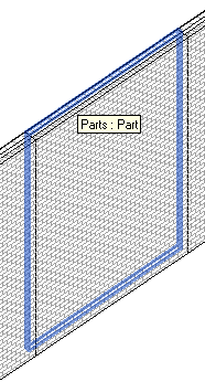
Faces of parts (which correspond to layers of a compound host object) can be offset via the API to achieve the same result that can be obtained in the UI by dragging the part's shape handles. This functionality provides customized control beyond the default layer configuration created by Revit.
Here is a wall converted to parts:
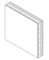
The wall part faces can be individually offset by the code below to produce this result:
  GeometryElement geomElem = part.get_Geometry( new Options() );

  foreach( GeometryObject geomObject in geomElem.Objects )
  {
    if( geomObject is Solid )
    {
      Solid solid = geomObject as Solid;
      FaceArray faceArray = solid.Faces;
      foreach( Face face in faceArray )
      {
        if( part.CanOffsetFace( face ) )
          part.SetFaceOffset( face, offsetCtr );
        offsetCtr += 0.1;
      }
    }
  }
Assemblies and Assembly Views
Assemblies are collections of elements that can be used in the Revit model to create shop drawings for prefabricated building components such as pre-cast walls, columns, beams, and floors. Assemblies can be scheduled, visually isolated, and tagged.
Every assembly has a primary element that determines the assembly's category. Each assembly is shown in the Project Browser and can be used to create assembly views that display only that assembly.
Read, write and create access to assemblies in the Revit environment is provided through the following two classes:
- Autodesk.Revit.DB.Assembly.AssemblyInstance
- Autodesk.Revit.DB.Assembly.AssemblyType
Other important methods include AssemblyInstance.GetMemberIds, AssemblyInstance.SetMemberIds, and AssemblyInstance.Disassemble.
Assembly Views display only the elements in the assembly and are created with methods of the AssemblyViewUtils class. The command below shows how assemblies and assembly views can be created with the API.
Here are two columns and a beam selected before running it:
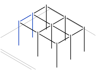
Running the command automatically creates an assembly and its associated views:
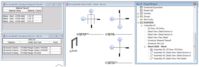
  Document doc = commandData.Application.ActiveUIDocument.Document;
  UIDocument uidoc = commandData.Application.ActiveUIDocument;

  ElementId categoryId = doc.get_Element( uidoc.Selection.GetElementIds().FirstOrDefault() ).Category.Id;

  if( AssemblyInstance.IsValidNamingCategory( doc, categoryId, uidoc.Selection.GetElementIds() ) )
  {
    Transaction transactionA = new Transaction( doc, "Create Assembly" );
    transactionA.Start();
    AssemblyInstance assemblyInstance = AssemblyInstance.Create( doc, uidoc.Selection.GetElementIds(), categoryId );
    transactionA.Commit(); // need to commit the transaction to complete the creation of the assembly instance so it can be accessed in the code below

    Transaction transactionB = new Transaction( doc, "Create Assembly Views" );
    transactionB.Start();
    assemblyInstance.AssemblyTypeName = "Assembly #1"; // rename the assembly
    if( assemblyInstance.AllowsAssemblyViewCreation() ) // check to see if views can be created for this assembly
    {
      ElementId titleblockId = doc.TitleBlocks.Cast<FamilySymbol>().First<FamilySymbol>().Id; // find a titleblock
      // create a sheet, 3d view, sections, a material takeoff, and parts list for this assembly
      ViewSheet viewSheet = AssemblyViewUtils.CreateSheet( doc, assemblyInstance.Id, titleblockId );
      View3D view3d = AssemblyViewUtils.Create3DOrthographic( doc, assemblyInstance.Id );
      ViewSection detailSectionA = AssemblyViewUtils.CreateDetailSection( doc, assemblyInstance.Id, AssemblyDetailViewOrientation.DetailSectionA );
      ViewSection detailSectionB = AssemblyViewUtils.CreateDetailSection( doc, assemblyInstance.Id, AssemblyDetailViewOrientation.DetailSectionB );
      ViewSection detailSectionH = AssemblyViewUtils.CreateDetailSection( doc, assemblyInstance.Id, AssemblyDetailViewOrientation.HorizontalDetail );
      View materialTakeoff = AssemblyViewUtils.CreateMaterialTakeoff( doc, assemblyInstance.Id );
      View partList = AssemblyViewUtils.CreatePartList( doc, assemblyInstance.Id );

      // Add graphical views to the newly created sheet. Schedules (the Parts List and Material Takeoff) cannot be added to sheets with the 2012 API.
      viewSheet.AddView( view3d, new UV( 1, 1 ) );
      viewSheet.AddView( detailSectionA, new UV( 1.3, 1 ) );
      viewSheet.AddView( detailSectionB, new UV( 1, 1.3 ) );
      viewSheet.AddView( detailSectionH, new UV( 1.3, 1.3 ) );
    }
    transactionB.Commit();
  }
  return Result.Succeeded;
For completeness' sake, here is the original handout document CP5211_Mattison.pdf itself.
If you log on to the AU web site, you will find that you have access to this very same handout document, and also to the original presentation, which I do not care to reproduce here, and 'additional materials', which turns out to be C# source code implementing three further external commands demonstrating Revit API functionality related to assemblies, groups and extensible storage:
- Create_Assembly_From_Group
- Update_Assemblies_From_Groups
- ReportStoredId
As far as I can tell, figuring out what they do and how they work is left as an exercise to the interested and motivated reader :-)
Many thanks to Harry and Enrique for this nice overview and all the sample code!