Create Section View Parallel to Wall
Here is a nice case that just came up and helped me heal my latent view manipulation phobia.
Before getting to that, a short pointer to a non-API issue: The Shanghai Tower is currently being built to become one of the tallest and greenest buildings in the world. Take a look at Shanghai Tower: The Role of BIM in Building the Spirit of the City, a six-minute video explaining the concept and the role of Autodesk BIM solutions in its design, construction, and operation.
Back to the view creation issue, the question is how to set up a section view that is parallel to a given wall.
The CreateViewSection SDK sample can be used as a basis for exploration, and the discussion on section view creation spells it out a bit further still. We also previously discussed some further aspects of elevation and section views and looked at setting up the view parameters to crop a 3D view to a room.
Obviously all previous explorations in the area of creating views make use of the obsolete view creation methods on the creation document class, which have now been replaced by static methods on the view classes themselves.
The only sample using the new methods was the recent one to create a structural plan view, without any need to explore the required transformation, view direction, or crop box.
To alleviate that, I implemented a new sample external command named CreateWallSectionView which expects a single straight perpendicular wall to be pre-selected and creates a section view parallel to the wall with its crop box set up to display the wall in its entirety.
The code is extremely straight-forward and actually worked right out of the box without any further tweaking.
It uses the wall location line as the main source of geometrical input. It also queries the wall bounding box to obtain its height, and uses the wall type Width property to determine the total wall thickness, although the latter is not used anywhere.
From the location line, it determines the wall direction and length. It sets up the bounding box min and max values from the length and height.
The transform is defined using the wall direction defining the right-left and the global world coordinate system Z vector defining the upward direction.
Simple and precise.
Here is the entire code achieving this:
[Transaction( TransactionMode.Manual )]
public class Command : IExternalCommand
{
  public Result Execute(
    ExternalCommandData commandData,
    ref string message,
    ElementSet elements )
  {
    UIApplication uiapp = commandData.Application;
    UIDocument uidoc = uiapp.ActiveUIDocument;
    Document doc = uidoc.Document;

    // Retrieve wall from selection set

    Selection sel = uidoc.Selection;

    SelElementSet set = sel.Elements;

    Wall wall = null;

    if( 1 == set.Size )
    {
      foreach( Element e in set )
      {
        wall = e as Wall;
      }
    }

    if( null == wall )
    {
      message = "Please select exactly one wall element.";

      return Result.Failed;
    }

    // Ensure wall is straight

    LocationCurve lc = wall.Location as LocationCurve;

    Line line = lc.Curve as Line;

    if( null == line )
    {
      message = "Unable to retrieve wall location line.";

      return Result.Failed;
    }

    // Determine view family type to use

    ViewFamilyType vft
      = new FilteredElementCollector( doc )
        .OfClass( typeof( ViewFamilyType ) )
        .Cast<ViewFamilyType>()
        .FirstOrDefault<ViewFamilyType>( x =>
          ViewFamily.Section == x.ViewFamily );

    // Determine section box

    XYZ p = line.get_EndPoint( 0 );
    XYZ q = line.get_EndPoint( 1 );
    XYZ v = q - p;

    BoundingBoxXYZ bb = wall.get_BoundingBox( null );
    double minZ = bb.Min.Z;
    double maxZ = bb.Max.Z;

    double w = v.GetLength();
    double h = maxZ - minZ;
    double d = wall.WallType.Width;
    double offset = 0.1 * w;

    XYZ min = new XYZ( -w, minZ - offset, -offset );
    XYZ max = new XYZ( w, maxZ + offset, 0 );

    XYZ midpoint = p + 0.5 * v;
    XYZ walldir = v.Normalize();
    XYZ up = XYZ.BasisZ;
    XYZ viewdir = walldir.CrossProduct( up );

    Transform t = Transform.Identity;
    t.Origin = midpoint;
    t.BasisX = walldir;
    t.BasisY = up;
    t.BasisZ = viewdir;

    BoundingBoxXYZ sectionBox = new BoundingBoxXYZ();
    sectionBox.Transform = t;
    sectionBox.Min = min;
    sectionBox.Max = max;

    // Create wall section view

    using( Transaction tx = new Transaction( doc ) )
    {
      tx.Start( "Create Wall Section View" );

      ViewSection.CreateSection( doc, vft.Id, sectionBox );

      tx.Commit();
    }
    return Result.Succeeded;
  }
}
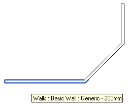
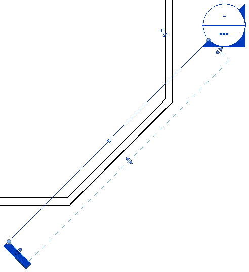
I tested the command in this simple project with three walls:
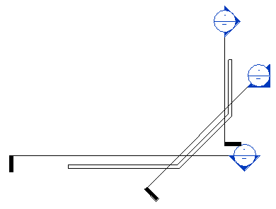
Here are the three section views created by running the command on all three walls:
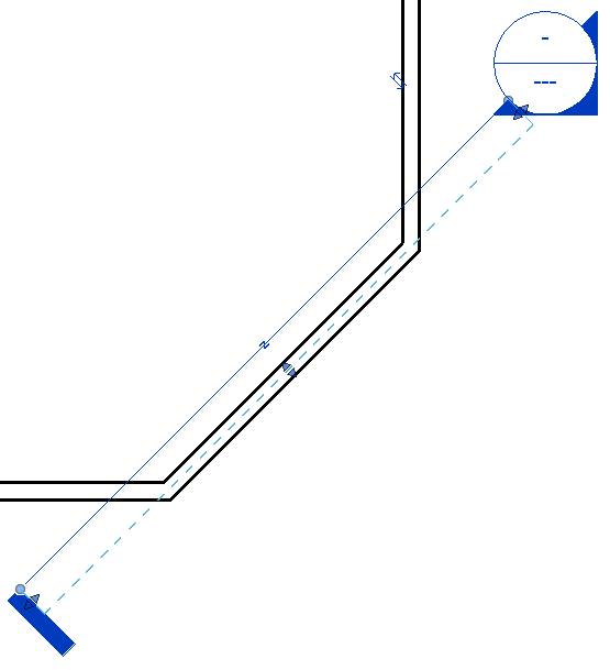
The resulting section views are quite reasonably positioned:
Sign on the Dotted Line, Please
Question: I need the section box to equally surround the wall on both sides.
The section box generated by the code above has its dotted line in the middle of the wall.
How can I move the section box dotted line so that it is offset out of the wall instead?
Answer: The Min and Max properties of the bounding box determine the crop region and far clip distance. In the code above, I defined
  XYZ min = new XYZ( -w, minZ - offset, -offset );
  XYZ max = new XYZ( w, maxZ + offset, 0 );
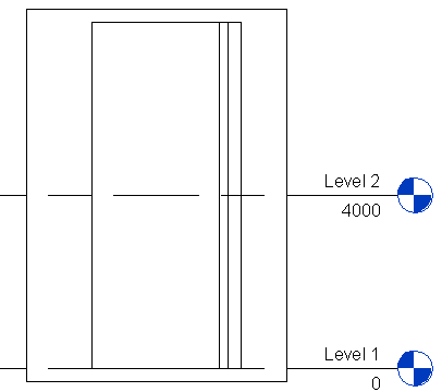
This produces the dotted line in the middle of the wall, like this:
If I change the Max property Z value from zero to +offset, the section view dotted line is offset from the wall in the way you wish:
  XYZ min = new XYZ( -w, minZ - offset, -offset );
  XYZ max = new XYZ( w, maxZ + offset, offset );
This produces the dotted line offset to the other side of the wall:
Perpendicular, not Parallel
Question: How can I set up the section view to be perpendicular to the wall and located at the wall centre point?
Answer: Well, obviously the same parameters as above apply.
Here is one little additional nice twist, though: instead of calculating the required transformation vectors based on the vector from the wall start point to its end point, we can obtain the wall location line curve tangent at its midpoint using the ComputeDerivatives method. The advantage of this is that it will work for a curved wall as well.
Here as the method GetSectionViewPerpendiculatToWall taking a wall input argument. It sets up and returns a section box for the section view creation at the wall midpoint and perpendicular to its location line. It takes the wall thickness and height into account to set up a crop box showing just the wall with one foot of space around it:
/// <summary>
/// Return a section box for a view perpendicular
/// to the given wall location line.
/// </summary>
BoundingBoxXYZ GetSectionViewPerpendiculatToWall(
  Wall wall )
{
  LocationCurve lc = wall.Location
    as LocationCurve;

  // Using 0.5 and "true" to specify that the
  // parameter is normalized places the transform
  // origin at the center of the location curve

  Transform curveTransform = lc.Curve
    .ComputeDerivatives( 0.5, true );

  // The transform contains the location curve
  // mid-point and tangent, and we can obtain
  // its normal in the XY plane:

  XYZ origin = curveTransform.Origin;
  XYZ viewdir = curveTransform.BasisX.Normalize();
  XYZ up = XYZ.BasisZ;
  XYZ right = up.CrossProduct( viewdir );

  // Set up view transform, assuming wall's "up"
  // is vertical. For a non-vertical situation
  // such as section through a sloped floor, the
  // surface normal would be needed

  Transform transform = Transform.Identity;
  transform.Origin = origin;
  transform.BasisX = right;
  transform.BasisY = up;
  transform.BasisZ = viewdir;

  BoundingBoxXYZ sectionBox = new BoundingBoxXYZ();
  sectionBox.Transform = transform;

  // Min & Max X values define the section
  // line length on each side of the wall.
  // Max Y is the height of the section box.
  // Max Z (5) is the far clip offset.

  double d = wall.WallType.Width;
  BoundingBoxXYZ bb = wall.get_BoundingBox( null );
  double minZ = bb.Min.Z;
  double maxZ = bb.Max.Z;
  double h = maxZ - minZ;

  sectionBox.Min = new XYZ( -2 * d, -1, 0 );
  sectionBox.Max = new XYZ( 2 * d, h + 1, 5 );

  return sectionBox;
}
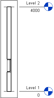
This produces the following section view through of a wall with a window in its midpoint:
Here is CreateWallSectionView.zip containing the entire source code, Visual Studio solution and add-in manifest for this command.