Retrieving Detailed Wall Layer Geometry
We start off the week with a bang. I find the following topic especially exciting, for several reasons:
- It deals with geometry. I like that.
- It implements something that cannot be achieved out of the box. I like that.
- It makes use of the Revit 2012 parts functionality and the PartUtils class, which we never looked at in detail before. I like that.
- It uses a temporary transaction to make changes to the model to create and extract information that would otherwise not be available, and then discards the changes to the model. I like that.
I hope you like it too!
Starting off this week with something special is good in several ways, because I will be leaving for a ten-day vacation in southern Spain on Wednesday. I like that too, by the way. I hope this helps keep you occupied while I am gone :-)
Here goes:
It is easy to determine the wall layer locations and their corner points individually for unconnected walls, as I demonstrated by analysing and drawing model lines to represent the wall compound layers way back in 2008. Some additional information on working with wall layers was provided when discussing compound wall layer volumes and the core structural layer.
However, it is a bit harder to determine the exact wall layer corners for connected walls, where the join type affects the layer geometry, e.g. for 'abut' or 'miter'.
How can we obtain the wall layer corner points in plan view taking the wall join into account?
This is a pretty advanced question on detailed geometry access which was raised by Marcelo Quevedo of hsbSOFT.
Solving this task is not achievable using the functionality provided by the Revit API out of the box, but can be addressed by making use of two interesting tricks:
- Splitting the wall into parts, which automatically take the wall layers into account.
- Embedding the split into a temporary transaction so that it can be rolled back without affecting the model afterwards.
This provides a welcome first opportunity to present a practical use of the Revit 2012 parts functionality and the PartUtils class providing API access to it.
The technique of using a temporary transaction for geometry analysis purposes was originally suggested by Scott Conover of the Revit API development team and already mentioned several times here in the past, e.g. for gross material quantity extraction.
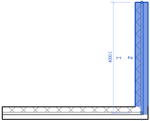
Question: I need to get the geometric information of the layers of a wall. Specifically, I need to retrieve the four corner points of a layer to know its position within the wall.
For example, if two walls are connected in a "Butt" type join, their layers are also connected using the same type join. I would like to obtain this geometry information about layers.
It would be very good if I can obtain the four points of a layer, or the two points. Here is an image explaining the problem:
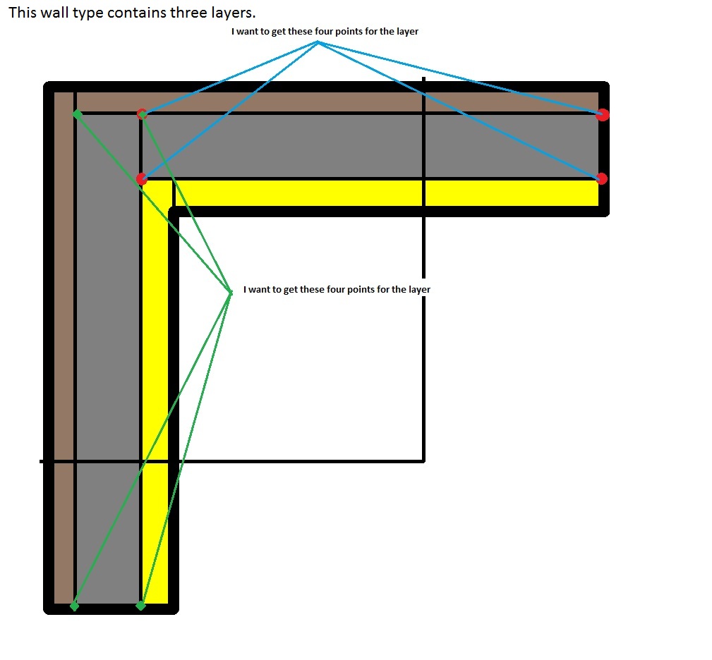
I can see from the blog posts you listed above how to retrieve the layers of a wall. However, when two or more walls are joined, e.g. using abut, miter etc., also their layers are joined in the same fashion. I want to get the four points of each layer:
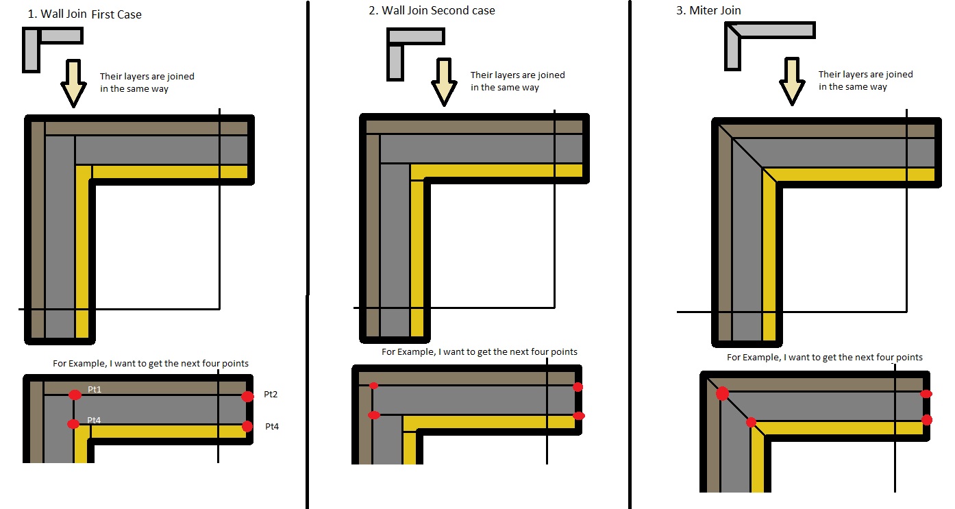
The four points are different depending on the wall join.
I looked into the Revit API help document, and I did find anything to access this information which is really necessary for us.
Could you please advise me how to achieve this?
Answer: The Revit API does not provide access to the geometrical information you seek out of the box. On the other hand, though, here is the good news:
You could try splitting the wall into parts. That will split it by layers. Then you can access the geometry of each part individually.
If you do so inside a temporary transaction that is rolled back afterwards, the model will remain unchanged.
Marcelo went ahead and implemented this, and the result works perfectly.
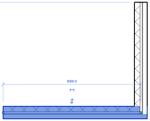
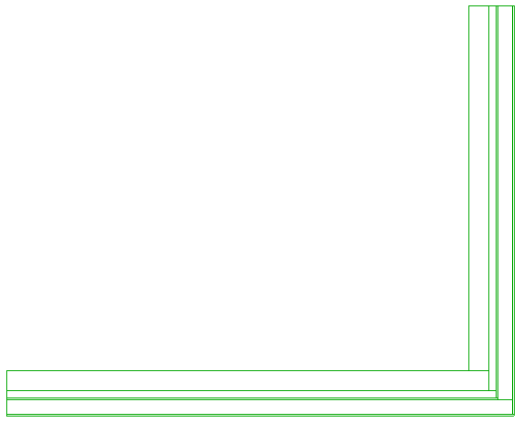
Here is a simple example of two walls with a compound internal layer structure:
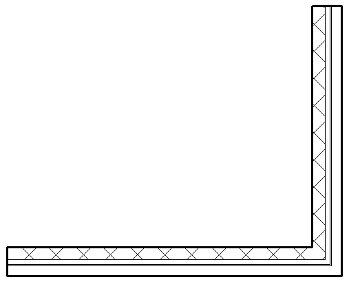
Selecting the walls one at a time shows you that the individual wall layers have different lengths:
The arrangement of the wall layer corner points is non-trivial:
Marcelo's sample application GeometryPartsAnalyzer implements the suggestion above, determines the geometry of each wall layer by converting it into an individual temporary part, determines the bottom face of each part, and creates model line geometry to display it:
The implementation includes several useful utility classes:
- FaceExtractor
- ModelLineCreator
- WallSelectionFilter
- CmdGeometryParts
The FaceExtractor queries a Revit element for its geometry, finds its solid, and extracts and returns all its faces.
Marcelo's ModelLineCreator is a simplified version of the model curve creator I maintain in The Building Coder samples and last used to display model lines representing the top faces of all walls.
The WallSelectionFilter is a trivial selection filter to ensure that only walls can be selected.
CmdGeometryParts implements the external command. It makes use of the helper method GetBottomFacePoints to retrieve a list of points representing the bottom face of the given Revit element:
public List<XYZ> GetBottomFacePoints( Element e )
{
  List<XYZ> resultingPts = new List<XYZ>();

  FaceExtractor faceExtractor
    = new FaceExtractor( e );

  FaceArray faces = faceExtractor.Faces;

  if( faces.Size == 0 ) { return resultingPts; }

  foreach( Face face in faces )
  {
    PlanarFace pf = face as PlanarFace;

    if( pf == null ) { continue; }

    if( pf.Normal.IsAlmostEqualTo( -XYZ.BasisZ ) )
    {
      EdgeArrayArray edgeLoops = face.EdgeLoops;

      foreach( EdgeArray edgeArray in edgeLoops )
      {
        foreach( Edge edge in edgeArray )
        {
          List<XYZ> points
            = edge.Tessellate() as List<XYZ>;

          resultingPts.AddRange( points );
        }
      }
    }
  }
  return resultingPts;
}
Here is the CmdGeometryParts mainline Execute method, which performs the following steps:
- Prompt the user to select the walls to process.
- Use the PartUtils class to check whether the selected walls can be split into parts.
- Start a temporary transaction for the part creation, so it can be rolled back later.
- Create the parts and regenerate the model so the part geometry becomes accessible.
- Extract the bottom faces of each part using the GetBottomFacePoints method.
- Roll back the temporary transaction to undo the splitting of walls into parts.
- Start a new transaction to create persistent model lines to display the part edges saved in the bottom face information.
- Create the model lines.
- Commit the second transaction.
Enjoy:
public Result Execute(
  ExternalCommandData cmdData,
  ref string msg,
  ElementSet elems )
{
  Result result = Result.Failed;

  UIApplication uiApp = cmdData.Application;
  UIDocument uiDoc = uiApp.ActiveUIDocument;
  Document doc = uiDoc.Document;

  Transaction transaction = new Transaction( doc );

  try
  {
    string strMsg = "Select walls";

    ISelectionFilter filter
      = new WallSelectionFilter();

    IList<Reference> walls
      = uiDoc.Selection.PickObjects(
        ObjectType.Element, filter, strMsg );

    if( walls.Count == 0 ) { return result; }

    List<ElementId> ids = new List<ElementId>();

    foreach( Reference reference in walls )
      ids.Add( reference.ElementId );

    if( !PartUtils.AreElementsValidForCreateParts(
      doc, ids ) )
    {
      return result;
    }

    transaction.Start( "parts" );

    // Split walls into parts

    PartUtils.CreateParts( doc, ids );

    // Regenerate document to get the part geometry

    doc.Regenerate();

    // Retrieve points from bottom faces of parts

    List<List<XYZ>> bottomFacesPts
      = new List<List<XYZ>>();

    foreach( ElementId id in ids )
    {
      if( !PartUtils.HasAssociatedParts( doc, id ) )
      {
        continue;
      }

      ICollection<ElementId> partIds
        = PartUtils.GetAssociatedParts(
          doc, id, true, true );

      foreach( ElementId partId in partIds )
      {
        Element part = doc.get_Element( partId );

        bottomFacesPts.Add(
          GetBottomFacePoints( part ) );
      }
    }

    // Do not affect the original state of walls

    transaction.RollBack();

    // Draw lines to show the bottom faces of parts

    transaction.Start();

    ModelLineCreator model
      = new ModelLineCreator( doc );

    foreach( List<XYZ> bottomFacePts in
      bottomFacesPts )
    {
      for( int i = 1; i < bottomFacePts.Count; ++i )
      {
        model.CreateLine( bottomFacePts[i - 1],
          bottomFacePts[i], true );
      }

      if( bottomFacePts.Count > 3 )
      {
        model.CreateLine( bottomFacePts[0],
          bottomFacePts[bottomFacePts.Count - 1],
          true );
      }
    }
    transaction.Commit();

    result = Result.Succeeded;
  }
  catch( System.Exception e )
  {
    msg = e.Message;
    result = Result.Failed;
  }
  return result;
}
Here is GeometryPartsAnalyzer.zip including the complete source code and Visual Studio solution of this command.
Many thanks to Marcelo for his exploration and nice implementation!