Slanted Column Cross Section Rotation
Here is a question that will be of most interest to people working with Revit Structure, on the different definitions of the cross section coordinate system of vertical versus slanted columns, with several people chipping in to answer it from various perspectives.
The solution is illuminating and highlights one significant difference between objects whose Location property is a LocationCurve versus a LocationPoint.
Question: Is there any rule or documentation on the definition of the cross section coordinate system orientation for structural beams and columns?
I am trying to export these elements from Revit Structure and using the right hand rule, but it seems to be sometimes producing the Y and sometimes the Z axis in the exported data.
On closer examination, I found that the problem is due to a difference between vertical and slanted columns in the definition of the cross section coordinate system; it is rotated by 90 degrees from one to the other.
Is this behaviour by design?
Answer (Miroslav Schonauer): Without even looking into what the Revit convention is, this is a typical "problem" (not a bug, but by-design) in all structural modelling/analysis software.
The issue is that the "rotation angle" (or sometimes called "orientation angle") has to be measured from some reference, i.e. default vector position. For non-vertical elements (i.e. broadly speaking "beams"), this "up-vector" is typically the global Z-axis projected to the plane perpendicular to the element curve-axis. However, for vertical elements (i.e. "columns"), global Z-axis is parallel with the curve-axis, hence the typical default "up vector" for them is assumed to be global Y-axis.
So, it is inevitable that the element would typically appear to "jump-rotate" when its position is changed from vertical to non-vertical. Of course, when this is done by just e.g. slightly adjusting the top end of previously vertical column, it all seems strange, but is mathematically unavoidable.
BTW, some packages tried to solve this by measuring the section orientation by directly stored full "orientation vector" rather than assuming default position + stored scalar value of angle. Then this orientation vector is projected to the element-axis perpendicular plane in order to place the section. But this is typically harder to manipulate and understand in the user interface. One can also change end-points so that the element axis becomes parallel with the orientation vector, so then its back to square one of the originating problem with element section "jumping" again ;-)
There may be some additional Revit-specific issues that I am not aware of, but I'm 99% sure this is the root of the "problem". Whoever has looked at a number of APIs dealing with these kinds of issues will have encountered this topic several times.
Answer (Aleksey Moiseyev): To the best of my knowledge, a column's Z direction is always along the direction of the column (as opposed to beams and braces).
However, the base direction for measuring the rotation angle is not based on element's local coordinates - it is, indeed, measured as described above, so a small slant may cause the profile to rotate.
Answer (Sasha Varsanofieva): Yes, Miro is correct on description of why rotation adjusts when the column becomes non-vertical. In non-vertical slanted columns, rotation is measured from the "up vector".
However, Revit actually has 3 states: Vertical Column, Vertical Slanted Column (Vertical, but 'column style' parameter set to slanted), and Slanted (Non-Vertical). If I understand the original issue correctly, the problem being reported is actually the transition between Vertical and Vertical Slanted, in which case both versions of the column are vertical. These two states do have different calculation of the transformation from the family coordinates to the column�s local coordinate system, but I don't expect the column to rotate when switching from one to the other.
More precisely, the calculations to establish the local coordinate system are different for vertical and vertical slanted columns. However, I have just tested this in Revit, and columns do not rotate when switched from vertical to slanted and vice versa. That leads me to suspect that this is an API only issue about reporting local coordinate systems of columns.
Answer (Joe Ye): After some deeper exploration, I found that there is indeed a significant difference between the cross section rotation handling of vertical and slanted columns.
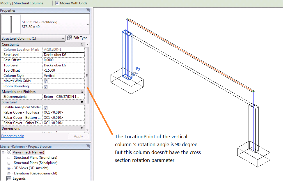
A vertical column has a LocationPoint value in its Location property, and the LocationPoint data includes its rotation information:

This rotation information is not displayed in the column properties:
The slanted column Location property, on the other hand, contains a LocationCurve instead of a LocationPoint. The LocationCurve class does not have any provision for managing any rotation data:

This does not mean that the slanted column rotation angle is missing, though. Instead, it stores its rotation information in an additional parameter named 'Cross-Section Rotation':

It is also interesting to create two vertical columns, change one of them to slanted, and compare their properties.
The appearance of the slanted one does not change.
Here are the slanted column properties:

Here are the vertical column properties:
