Curtain Wall Geometry
Last week, I did some work exploring the geometry available in a curtain wall instance. It led to several interesting results:
- An exploration of the relationship between a curtain wall and its panels.
- Direct access to the curtain wall geometry using the geometry options IncludeNonVisibleObjects property.
- A new model curve creator method.
- FootPrintRoof and CurtainSystem geometry.
The starting point for all this was the following question:
Question: I'm trying to retrieve the geometric curves, i.e. lines and arcs, that defining the perimeter of a wall element using the Curtain Wall system family. Unfortunately, the Wall.Geometry.Objects' EdgeArray and FaceArray are empty. This is not true for other types of walls.
How can I retrieve the X, Y and Z coordinates of the curtain wall profile?
The profile is displayed in the user interface as dashed lines marking the perimeter of the curtain wall when the cursor hovers over it:
Answer: The curtain wall does indeed not have any geometry of its own when queried using the default geometry option settings. We will see below that there is a useful option setting which returns more detailed results. Before looking into that, we will have a look at the associated panel elements which manage the visible standard geometry.
Relationship between a curtain wall and its panels
To explore the relationship between a curtain wall and its panels, I created a sample model and added a new curtain wall, using the element lister implemented in Lab2_1_Elements in the Revit API introduction labs to determine what new elements get added by that step.
Here is how I use it to determine the curtain wall and the panel:
- Start up Revit and open a new project.
- Run Lab2_1_Elements to create C:\tmp\RevitElements.txt.
- Rename the resulting file to RevitElementsBeforeCurtainWall.txt.
- Create a curtain wall and run Lab2_1_Elements again.
- Rename the resulting file to RevitElementsAfterCurtainWall.txt.
The newly added elements in my model in Revit Architecture 2011 are:
C:\tmp\ >diff
  RevitElementsBeforeCurtainWall.txt
  RevitElementsAfterCurtainWall.txt
2842a2843,2844
> Id=149169; Class=Wall; Category=Walls; Name=Curtain Wall
> Id=149170; Class=Panel; Category=Curtain Panels; Name=Glazed
I tried the same steps in Revit Architecture 2010 with an analogous result:
C:\tmp\ >diff
  RevitElementsBeforeCurtainWall2010.txt
  RevitElementsAfterCurtainWall2010.txt
2255a2256,2257
> Id=130424; Class=Wall; Category=Walls; Name=Curtain Wall
> Id=130425; Class=Panel; Category=Curtain Panels; Name=Glazed
So the problem that needs to be solved is how to determine the relationship between the curtain wall and its associated panels.
By the way, I initially used this same technique to explore the relationship between a stacked wall and it basic wall components, with quite similar results.
If your application is creating the curtain wall itself, it can keep track of their ids when they are created. It could create and temporarily store a list of all element ids before creating the curtain wall, and then again afterwards. The newly added ids will be related to the curtain wall and its panel as shown above.
If you do not have the possibility to set such checkmarks before and after creating the curtain wall, you might still be able to use the fact that the associated ids are consecutive.
Happily, several more reliable ways to determine the relationships between elements also exist.
One is to delete the main element inside a sub-transaction that is later aborted, and see what elements are deleted with it, as demonstrated by the object relationship viewer (in VB).
Better still is to use geometrical analysis. The curtain wall itself does not have any accessible geometry objects, as you have seen, but you can still use its bounding box or location curve to determine its position in the model.
The panel does have valid geometry, as we can determine by examining it using RevitLookup, stepping through the following hierarchy: Snoop DB > Panel > Glazed 149170 > Geometry > Objects > Symbol geometry > Objects > Edges and Faces.
The panel instance geometrical objects are originally defined in the symbol definition local coordinate system and you need to apply the instance transform to them to retrieve the world coordinate system data, i.e. apply Snoop DB > Panel > Glazed 149170 > Geometry > Objects > Symbol geometry > Transform
This is described in the analysis of instance coordinate transformation.
Using the position of the curtain wall determined from its location line or bounding box, and the geometry of the panel, you can determine their relationship to each other by checking for overlap or adjacency. One way to checking for adjacency is to use the FindReferencesByDirection method. This should work, using the curtain wall location line to define the starting point of the ray and then shooing it in various directions to intersect the panel geometry.
You could also simply determine specific points on the location line and the panel geometry and check whether the volumes defined by each overlap.
So given the element id of the curtain wall or the panel, you can use this technique to search for the other associated element. In a large model, one would obviously want to add additional criteria to limit the search to as few candidate elements as possible. You could use the curtain wall and panel types, for instance, if these are known. You might be able to use the BoundingBoxIntersectsFilter class, although again, this might only work for the panel, which has accessible geometry, and maybe not for the curtain wall. One criterion which you can definitely use is the level property, which is defined on both the curtain wall and the panel.
Direct Access to the Curtain Wall Geometry
However interesting this exploration of the relationship between the curtain wall and its panels may seem, it would be nice to have a more direct access to the curtain wall perimeter without having to perform a complex analysis of the associated panel geometry.
If the wall was created from a mass, then the perimeter lines can be retrieved from the mass face edge loops. If not, one might try to retrieve the curtain wall LocationCurve and calculate the perimeter lines with the height.
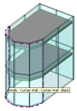
However, there is a pretty perfect and much simpler method that took some exploration to discover: simply setting the geometry options IncludeNonVisibleObjects property. This provides access to the geometry of an internal "hidden" wall that Revit uses to represent the curtain wall and the lines and arcs with Visibility=Highlight, which seems to be exactly what we are looking for. Here is a sample curtain wall:
Here is some code to set the geometry options IncludeNonVisibleObjects property and retrieve and list the curves:
void list_wall_geom( Wall w, Application app )
{
  string s = "";

  CurtainGrid cgrid = w.CurtainGrid;

  Options options
    = app.Create.NewGeometryOptions();

  options.ComputeReferences = true;
  options.IncludeNonVisibleObjects = true;

  GeometryElement geomElem
    = w.get_Geometry( options );

  foreach( GeometryObject obj
    in geomElem.Objects )
  {
    Visibility vis = obj.Visibility;

    string visString = vis.ToString();

    Arc arc = obj as Arc;
    Line line = obj as Line;
    Solid solid = obj as Solid;

    if( arc != null )
    {
      double length = arc.ApproximateLength;

      s += "Length (arc) (" + visString + "): "
        + length + "\n";
    }
    if( line != null )
    {
      double length = line.ApproximateLength;

      s += "Length (line) (" + visString + "): "
        + length + "\n";
    }
    if( solid != null )
    {
      int faceCount = solid.Faces.Size;

      s += "Faces: " + faceCount + "\n";

      foreach( Face face in solid.Faces )
      {
        s += "Face area (" + visString + "): "
          + face.Area + "\n";
      }
    }
    if( line == null && solid == null && arc == null )
    {
      s += "<Other>\n";
    }
  }
  TaskDialog.Show( "revit", s );
}
The output returned for the wall above looks like this:
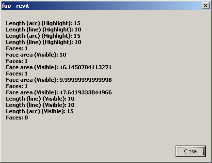
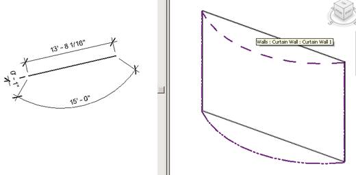
I applied this setting to the model with an arced curtain wall shown above. I asked the curtain wall for its geometry with IncludeNonVisibleObjects set to true, and then generated model lines offset by the length of the wall from the geometry returned by that call:
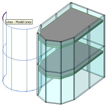
Model Curve Creator Method
To generate the model curves shown above, I made some enhancements to The Building Coder sample Creator class, which we will present in detail in a future post.
FootPrintRoof and CurtainSystem Geometry
Joe Offord of enclos corp., who initially raised this question, provided some further information on using the same technique to retrieve geometry from other elements as well. Says Joe:
I ran across some other loops I had to jump through.
What my program does is export all the curtain wall mullion geometry from Revit into an analytical software package.
Based on our discussion, I was able to retrieve the X,Y,Z of each end of each mullion that was hosted by a System Family - Curtain Wall. But because architects like to dream up exotic shapes for glass structures, there may also exist curtain wall systems on non-vertical surfaces in the model. Thus, I also had to export out CurtainSystems and RoofFootPrint elements that might contain CurtainGrids and Mullions.
Because CurtainGrids can be hosted by objects other than walls, I had to include these additional elements in my coding. As far as I could tell, the GeometryObjects of these elements had to be one of three types: Line, Arc, or HermiteSpline. I could retrieve the end points I needed from all of these. The HermiteSpline elements usually occurred on sloped roofs with curved boundaries.
Using the same logic as the walls, I found X,Y,Z coordinates for the non-visible border of RoofFootPrints and CurtainSystems, as well as X,Y,Z coordinates of all the interior nodes using CurtainGridLines.ExistingSegments.
Many thanks to Joe for the fruitful discussions on this subject!