Face Edges
This is part 6 of Scott Conover's AU 2009 class on analysing building geometry.
Edge and Face Parameterization
Edges are boundary curves for a given face.
Iterate the edges of a Face using the EdgeLoops property. Each loop represents one closed boundary on the face. Edges are always parameterized from 0 to 1.
An edge is usually defined by computing intersection of two faces. But Revit doesn't recompute this intersection when it draws graphics. So the edge stores a list of points – end points for a straight edge and a tessellated list for a curved edge. The points are parametric coordinates on the two faces. These points are available through the TessellateOnFace method.
Sections produce 'cut edges'. These are artificial edges – not representing a part of the model-level geometry, and thus do not provide a Reference.
Edge Direction
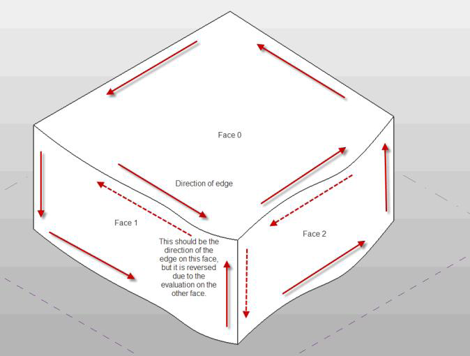
Direction is normally clockwise on the first face (first representing an arbitrary face which Revit has identified for a particular edge). But because two different faces meet at one particular edge, and the edge has the same parametric direction regardless of which face you are concerned with, sometimes you need to figure out the direction of the edge on a particular face.
The figure below illustrated how this works. For Face 0, the edges are all parameterized clockwise. For Face 1, the edge shared with Face 0 is not re-parameterized; thus with respect to Face 1 the edge has a reversed direction, and some edges intersect where both edges' parameters are 0 (or 1):
The PanelEdgeLengthAngle Revit SDK Sample
The Revit SDK sample PanelEdgeLengthAngle shows how to recognize edges that are reversed for a given face. It uses the tangent vector at the edge endpoints to calculate the angle between adjacent edges, and detect whether or not to flip the tangent vector at each intersection to calculate the proper angle:

The next instalment of this series will look at transformations.