Editing a Floor Profile
A question that recently came up was how to edit an existing floor profile. This also leads to the question of whether one can access the existing sketch lines through the API and modify them.
In the user interface, one can enter the Floor Edit mode and modify the sketch lines of a floor. In the API, this is not possible. However, it is possible to simply recreate the floor with a new curve array.
The next question that pops up is how to determine the sketch lines of the existing floor, as a starting point for recreating a new floor with a slightly modified set of sketch lines.
To recreate a floor from the existing one, one can determine the topmost horizontal face of the floor solid, using an algorithm very similar to the one we looked at for determining the slab boundary. We can extract the top face edges, create line elements from them to assemble the floor profile, and generate the new floor from that. In case the existing floor has holes in it, the face will have several loops. The largest loop is the outer perimeter. In my tests so far, this was also the first loop in the EdgeArrayArray, but that may not always be true.
Here is a helper method to extract the topmost face from the solid:
PlanarFace GetTopFace( Solid solid )
{
  PlanarFace topFace = null;
  FaceArray faces = solid.Faces;
  foreach( Face f in faces )
  {
    PlanarFace pf = f as PlanarFace;
    if( null != pf
      && Util.IsHorizontal( pf ) )
    {
      if( (null == topFace)
        || (topFace.Origin.Z < pf.Origin.Z) )
      {
        topFace = pf;
      }
    }
  }
  return topFace;
}
Here is the code for the rest of the command:
public CmdResult Execute(
  ExternalCommandData commandData,
  ref string message,
  ElementSet elements )
{
  Application app = commandData.Application;
  Document doc = app.ActiveDocument;

  List<RvtElement> floors = new List<RvtElement>();
  if( !Util.GetSelectedElementsOrAll(
    floors, doc, typeof( Floor ) ) )
  {
    Selection sel = doc.Selection;
    message = ( 0 < sel.Elements.Size )
      ? "Please select some floor elements."
      : "No floor elements found.";
    return CmdResult.Failed;
  }

  int nNullFaces = 0;
  List<Face> topFaces = new List<Face>();
  Options opt = app.Create.NewGeometryOptions();

  foreach( Floor floor in floors )
  {
    GeoElement geo = floor.get_Geometry( opt );
    GeometryObjectArray objects = geo.Objects;
    foreach( GeometryObject obj in objects )
    {
      Solid solid = obj as Solid;
      if( solid != null )
      {
        PlanarFace f = GetTopFace( solid );
        if( null == f )
        {
          Debug.WriteLine(
            Util.ElementDescription( floor )
            + " has no top face." );
          ++nNullFaces;
        }
        topFaces.Add( f );
      }
    }
  }

  Autodesk.Revit.Creation.Application creApp = app.Create;
  Autodesk.Revit.Creation.Document creDoc = doc.Create;

  int i = 0;
  int n = topFaces.Count - nNullFaces;

  Debug.WriteLine( string.Format(
    "{0} top face{1} found.",
    n, Util.PluralSuffix( n ) ) );

  foreach( Face f in topFaces )
  {
    if( null != f )
    {
      CurveArray profile = new CurveArray();
      EdgeArrayArray eaa = f.EdgeLoops;

      EdgeArray ea = eaa.get_Item( 0 );
      foreach( Edge e in ea )
      {
        XYZArray pts = e.Tessellate();
        int m = pts.Size;
        XYZ p = pts.get_Item( 0 );
        XYZ q = pts.get_Item( m - 1 );
        Line line = creApp.NewLineBound( p, q );
        profile.Append( line );
      }
      Floor floor = floors[i++] as Floor;
      floor = creDoc.NewFloor( profile, floor.FloorType, floor.Level, true );
      doc.Move( floor, new XYZ( 5, 5, 0 ) );
    }
  }
  return CmdResult.Succeeded;
}
The first section retrieves selected floors from the current selection set, or all floors from the database, if nothing has been preselected. Then the top face of each selected floor is determined by retrieving each floor's solid and calling GetTopFace on it. Even if no top face was found, we still store the null result, so that the list of floors and faces match up. Finally we go through the array of top faces and create new floors from them. Before creating the new floor, we would obviously apply whatever modifications are required to the new floor profile. In this case, we have no modifications to apply, so the new floor will be identical to the existing one. To differentiate it, we move it away from the original location, five feet up and to the right. In case the original floor had some non-linear edges, these will be replaced by straight ones. All holes will also be lost. From the EdgeArrayArray instance returned by the face EdgeLoops property, we only make use of the first element, which seems to be the outer perimeter, i.e. boundary. Holes seem to be listed later in this array. If this assumption is not true, we would have to iterate over the array and analyse each loop to find the maximum size, which would ensure that is the outer boundary and not an inner hole loop.
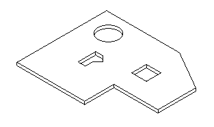
Here is a sample floor element before running the command:
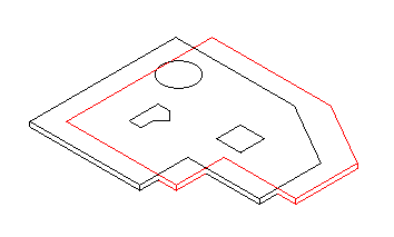
Here is the original floor and the newly created copy offset from it and lacking holes after running the command:
I am adding a new version 1.0.0.11 of the complete Visual Studio solution here (file no longer available), including the new CmdEditFloor and all other commands discussed so far.