Link Filter, Ceiling and Link Hatch Dim Voodoo
Fresh looks at dimensioning voodoo with stable representations, accessing and filtering elements in linked files, and transient graphics for jigs:
- Stable representation voodoo for hatch dimensions
- Dimensioning hatch pattern on ceiling
- Dimensioning hatch pattern in linked file
- Final solution code
- Filter elements in linked file
- RubberBand jig
Stable Representation Voodoo for Hatch Dimensions
Fair59 shared some powerful stable representation voodoo for obtaining references to hatch pattern lines on a floor slab to programmatically dimension on hatch pattern way back in 2017, in the Revit API discussion forum threads on dimension on hatch pattern slab and use of align function to programatically change the alignment of tiles for floor. Some further aspects have been added in the meantime to handle floors as well as ceilings, and hatch atterns in linked files.
Dimensioning Hatch Pattern on Ceiling
Chuong Ho added a solution to switch from the original solution for ceilings to floors:
Recenlly, I tried to find the pick first point intersect of pattern and succeeded, but when you change between Floor and Ceiling, you need to change the number step of pattern:
Floor:
int index = 2 + (ip * _gridCount * 2);
int index = 3 + (ip * _gridCount * 2);
Ceiling:
int index = 1 + (ip * _gridCount * 2);
int index = 2 + (ip * _gridCount * 2);
Example to find the first intersect of pattern :
public XYZ? FindPlacePointPattern()
{
  using Autodesk.Revit.DB.Transaction tran = new Transaction(Doc, "Find Place Point Pattern");
  tran.Start();
  //check for model surfacepattern
  var hostObject = this.HostObjectPart.HostObject;
  Reference? top = HostObjectUtils.GetTopFaces(hostObject)
    .FirstOrDefault();
  PlanarFace? topFace = hostObject.GetGeometryObjectFromReference(
    top) as PlanarFace;
  Material mat = Doc.GetElement(
    topFace.MaterialElementId) as Material;
  ElementId foregroundPatternId = mat.SurfaceForegroundPatternId;
  FillPatternElement? patterntype = Doc.GetElement(
    foregroundPatternId) as FillPatternElement;
  FillPattern pattern = patterntype.GetFillPattern();
  if (pattern.IsSolidFill || pattern.Target == FillPatternTarget.Drafting) return null;

  // get number of gridLines in pattern
  int _gridCount = pattern.GridCount;
  //https://forums.autodesk.com/t5/revit-api-forum/dimension-on-hatch-pattern-slab/m-p/7078368#M22785
  // construct StableRepresentations and find the Reference to HatchLines
  string StableRef = top.ConvertToStableRepresentation(Doc);
  ReferenceArray _resArr = new ReferenceArray();
  for (int ip = 0; ip < 2; ip++)
  {
    int index = 2 + (ip * _gridCount * 2);
    string StableHatchString = StableRef + $"/{index}";
    var HatchRef = Reference.ParseFromStableRepresentation(Doc, StableHatchString);
    _resArr.Append(HatchRef);
  }

  // 2 or moreReferences => create dimension
  Dimension d1 = null;
  if (_resArr.Size > 1)
  {
    d1 = Doc.Create.NewDimension(Doc.ActiveView,
      Line.CreateBound(XYZ.Zero, new XYZ(1, 0, 0)), _resArr);
    // move dimension a tiny amount to orient the dimension perpendicular to the hatchlines
    // I can't say why it works, but it does.
    ElementTransformUtils.MoveElement(Doc, d1.Id, new XYZ(.01, 0, 0));
  }

  _resArr.Clear();
  for (int ip = 0; ip < 2; ip++)
  {
    int index = 3 + (ip * _gridCount * 2);
    string StableHatchString = StableRef + $"/{index}";
    var HatchRef = Reference.ParseFromStableRepresentation(Doc, StableHatchString);
    _resArr.Append(HatchRef);
  }

  // 2 or more References => create dimension
  Dimension? d2 = null;
  if (_resArr.Size > 1)
  {
    d2 = Doc.Create.NewDimension(Doc.ActiveView,
      Line.CreateBound(XYZ.Zero, new XYZ(0, 1, 0)), _resArr);
    // move dimension a tiny amount to orient the dimension perpendicular to the hatchlines
    // I can't say why it works, but it does.
    ElementTransformUtils.MoveElement(Doc, d2.Id, new XYZ(0, .01, 0));
  }
  // create dimension between two dimensions


  // try get cross point of two dimensions
  if (d1 != null && d2 != null)
  {
    XYZ? intersection = FindIntersectByTwoDirection(d1, d2);
    return intersection;
  }

  tran.RollBack();
  return null;
}
Dimensioning Hatch Pattern in Linked File
Jorge Morente took a look at the same issue working with linked files:
Many thanks to @Chuong.Ho and especially to @Fair59 for this very valuable information. I have used this code and it works perfectly for me. I managed to center elements in the ceiling grid when I have the ceiling and the element in the same model. What happens when the ceiling is in a linked model? I tried it and I have a problem.
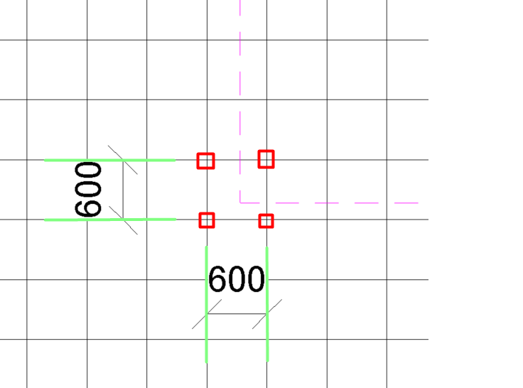
What I do to get a point from the grid and from there 2 perpendicular lines is to get the origin of each dimension, add or subtract half the value of one of the grid cells, and I have the point positioned on the line. I create a line with the point and direction, and I have "the axes" of the grid. This worked perfectly in my initial case, but not with the ceiling in a linked model:

As seen in the image, I have the 2 dimensions from which I can obtain any of the green lines and thus any of the 4 red points. But the point I get with the script is the origin of the pink lines. It is displaced and I don't know why.
At first, I thought it could be because the origin point of the linked model was offset, but no, I checked and it is at (0,0,0). I can't figure out what it could be.
Update 1: In the previous example, I had ceilings in both the model and the linked model, and it seems I was mixing things up that I shouldn't have.
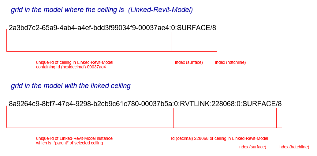
I created a model from scratch where I only have one ceiling, and it's from a linked model, and I've detected the problem. The references we created by adding some indices at the end to create the dimensions are not valid because the references I need have this structure:
- 33899bce-a21c-4067-af38-2260a13fa4e9-00023f0b:0:RVTLINK:147216:1/181
I use this statement:
StableRef = bottom.ConvertToStableRepresentation(linkedDocument);That returns the following value:
- f6c5042c-3953-4e47-afb0-42e0e62b1e73-00023f10:1:SURFACE
Curiously, if I dimension the grid in the model where the ceiling is, the references are with the code f6c5042... which is the UniqueId of the ceiling. If I dimension it in the model with the linked ceiling, the dimension references are 33899bce.... It's as if Revit renames the references, and I have no way of obtaining them from the ceiling because they are not those.
Answer: Fair59's new answer is an image. Does it say more than a thousand words? It says enough, anyway:

Many thanks to Fair59 for the succinct solution.
Final Solution
Jorge shared the complete final code, saying:
It works perfectly for simple patterns, both in the model and in links:
int gridCount = pattern.GridCount;

for (int i = 1; i < 3; i++)
{
  for (int ip = 0; ip < 2; ip++)
  {
    int index = i + (ip * gridCount *2);

    string StableHatchString = null;
    if (isLinked)
    {
      var uniqueId = revitLinkInstance.UniqueId;
      string indexSurface = StableRef.Length >= 10 ?
      StableRef.Substring(StableRef.Length - 10) : StableRef;
      StableHatchString = $"{uniqueId}:0:RVTLINK:{ceilingInstance.Id}
                         {indexSurface}/{index}";
    }
    else
    {
      StableHatchString = StableRef + $"/{index}";
    }

    Reference HatchRef = null;
    HatchRef = Reference.ParseFromStableRepresentation(document,
               StableHatchString);

    if (HatchRef == null)
    {
      continue;
    }

    _resArr.Append(HatchRef);
  }

  // 2 or more References => create dimension
  Dimension dimension = null;
  if (_resArr.Size > 1)
  {
    dimension = document.Create.NewDimension(document.ActiveView,
          Line.CreateBound(XYZ.Zero, new XYZ(1, 0, 0)), _resArr);
    ElementTransformUtils.MoveElement(document, dimension.Id,
                                        new XYZ(.01, 0, 0));
  }

  dimensions.Add(dimension);
  _resArr.Clear();
}
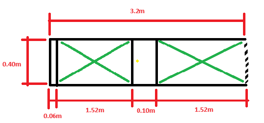
I tested it with a ceiling that has a more complex pattern, with a gridCount of 6, 2 horizontally and 4 vertically, and had to change the index formula because it was giving me the same dimension:
int index = i + 2 + (ip * gridCount * 2);No guarantee that it will work in other cases where the gridCount is not equal to 2.
This is the pattern:

I managed to place the element in the center of the pattern, represented by the yellow dot. The goal was to place it at one of the intersections of the green lines. I think it's very complicated when the patterns aren't simple, and not worth the effort.
Thanks to everyone who helped solve this problem.
Filter Elements in Linked File
Continuing with linked files, the filtered element collector provides a helpful constructor taking separate element ids for the view and the link instance to filter for elements in a linked file in a specific view in the main project file, as we (re-) discovered discussing in StackOverflow how to filter elements in linked files:
Question: I'm using Python, pyRevit and Revit 2021.
Goal:
I want to use the FilteredElementCollector in order to collect specific elements within Revit Links linked in my project.
Problem:
My question is how do I collect only the elements that are in my current view and belongs to Revit Links?
Im not sure about what I tried because I am working on a big file with multiple Revit Links and when I try to print the elements I get an endless list of elements inside every Link, which doesnt seem right given the fact that my current view is a section with not a lot of elements in it.
link_doc.ActiveView.Id produces a NoneType error –
but when not passing an active view I get that endless list of elements I mentioned.
Script:
doc = __revit__.ActiveUIDocument.Document # type: Document
uidoc = __revit__.ActiveUIDocument # type: UIDocument
selection = uidoc.Selection # type: Selection

# Collect all Revit Link instances
revit_link_instances_collector = FilteredElementCollector(doc, active_view.Id).OfClass(RevitLinkInstance).ToElements()
for link in revit_link_instances_collector:
  # Get the doc for current Link
  link_doc = link.GetLinkDocument()
  if link_doc:
    # collect all FamilyInstances
    linked_elemens = FilteredElementCollector(link_doc, link_doc.ActiveView.Id).OfClass(FamilyInstance).WhereElementIsNotElementType().ToElements()
    for element in linked_elemens:
      print(element)
Answer:
Yes, you need to keep careful track of which document owns the view and the elements you seek. The active view is in the current document A. The elements that you are looking for are in the linked document B. When you use the FilteredElementCollector(Document doc, ElementId view_id) constructor, it returns a new FilteredElementCollector that will search and filter the visible elements in doc in the specified view that also has to belong to doc. So, I do not believe you can use that functionality for the case you describe.
Wow, researching this question a bit further, I discovered an answer in the Revit API discussion forum that solves this issue, on how to filter visible elements from linked Revit model.
The solution is to use a new FilteredElementCollector constructor overload taking two view element ids: FilteredElementCollector(Document, ElementId, ElementId) constructs a new FilteredElementCollector that will search and filter the visible elements from a Revit link in a host document view.
Oh dear, I see that you mention Revit 2021. The new overload was apparently introduced in Revit 2024, almost two years ago.
To quote from Richard Thomas' answer: Prior to 2024 getting visibility of elements in link per view is non-existent I believe. You can approximate with some element filters transferred into the link document but they will not pick up if the element has been hidden in view in the document that hosts the link.
One idea would be to transfer the view itself to the link document (transformed to correct position for link instance) and use the FilteredElementCollector on it there. I've not tried that myself but see no obvious reasons why it would not work. You will not get the elements from the host document that way but those can be added separately.
RubberBand Jig
Mauricio @Speed_CAD Jorquera enhanced his RubberBand solution:
A while ago I created a method to emulate a RubberBand when selecting two points. I recently had time to separate the project and share it on my GitHub. The complete code is available in case anyone wants to improve it, and I hope that in the future Autodesk will release a native method for this. The link is as follows:
Many thanks to Mauricio for sharing this.
More transient graphics and jig examples: