No Geometry, Touching Geometry and Cut Geometry
Discussions of BIM, geometry, pyRevit and AI news:
- pyRevit discourse
- The BIM has no geometry
- Get touching elements
- What is a stable representation of a reference?
- CUT_EDGE reference voodoo
- Revit and IFC coordinate systems
- Chinese influencer deepfakes livestreaming 24/7
- Generative AI use and misuse
pyRevit Discourse
I just discovered the recommendation to direct all pyRevit questions to the dedicated pyRevit discussion forums:
... questions related to pyRevit should be routed to discourse.pyrevitlabs.io. This type of question has been formulated or answered in many different ways there; search for subprocess...
Thanks to Jean-Marc Couffin of BIM One Inc for pointing this out in the Revit API discussion forum thread on CPython and PyRevit.
The BIM has No Geometry
One fundamental and possibly surprising aspect of the BIM: it has no geometry. This came up in the thread on how to simplify elements geometry:
Question: I am trying to simplify the geometry of elements such as cylinders, spheres, etc. through the API. My first idea was simple:
- Retrieve a mesh from all faces with low quality using
face.Triangulate(0) - Apply the new mesh to the element geometry
However, it does not work. I have seen messages on the forum stating that working with geometry through the API is not allowed. Anyway, I believe that there it should be another approach to tackle this issue.
Answer: No. There is no way that you can specify Revit element geometry. Please bear in mind that Revit is a BIM authoring tool. The BIM is completely driven by parameters and constraints.
There is no geometry in the BIM!
The model as you see it (and its geometry) is just a view of the elements, their relationships, parameters and constraints.
Get Touching Elements
In spite of that, we keep running into tasks that are intimately involved with the BIM element geometry, such as the retrieval of cut edges between intersecting elements discussed below and the following task to get touching elements:
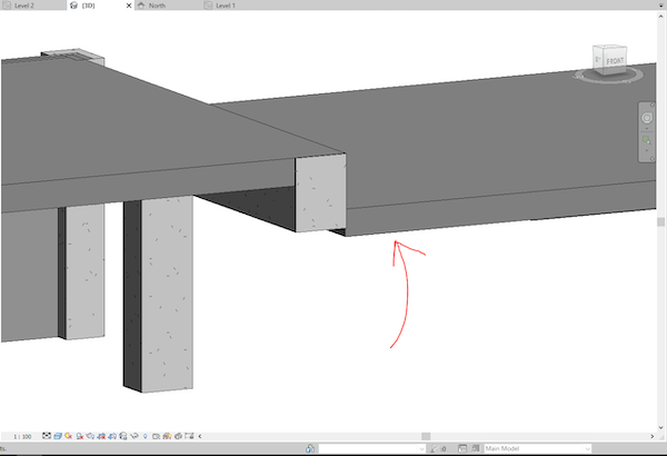
Question: I want to get the slabs that are on the edge of a beam as shown in this figure:

How can I get these slabs?
ElementIntersectsElement and ElementIntersectsSolid don't work in this case.
Answer: You should be able to use ElementIntersectsSolid with a slightly enlarged solid.
If your beam is aligned with one of the cardinal axes, you could even use a BoundingBoxIntersectsFilter instead, which is a quick filter.
Just make the bounding box a bit bigger than the beam.
If worst comes to worst, you can also use the ReferenceIntersector to shoot rays from the beam to detect the neighbouring slab.
Finally, though, and best of all, 11 years ago, The Building Coder presented a solution to filter for touching beams using solid intersection
Response: Thank you, that solution helped a lot.
I made a solution where I used the location line and some transform functions.
Then, the solid.IntersectsWithCurve method enabled me to retrieve the slabs.
What is a Stable Representation of a Reference?
As mentioned above, the BIM database does store any geometry. And yet, the BIM annotation contains database elements such as dimensioning that refer to the geometry, and even to geometry sub-elements such as cut edges generated by element intersection.
How can that be?
Well, the dimensioning requires a reference, and since the reference itself disappears when the geometry is gone, Revit uses the concept of a stable representation of the reference to store information about which reference we mean, even if the geometry is gone, cf., e.g., this brief explanation of reference and stable representation.
CUT_EDGE Reference Voodoo
Joseph Tenenbaum shares a new application of stable reference magic voodoo in his solution
to retrieve CUT_EDGE references from walls:
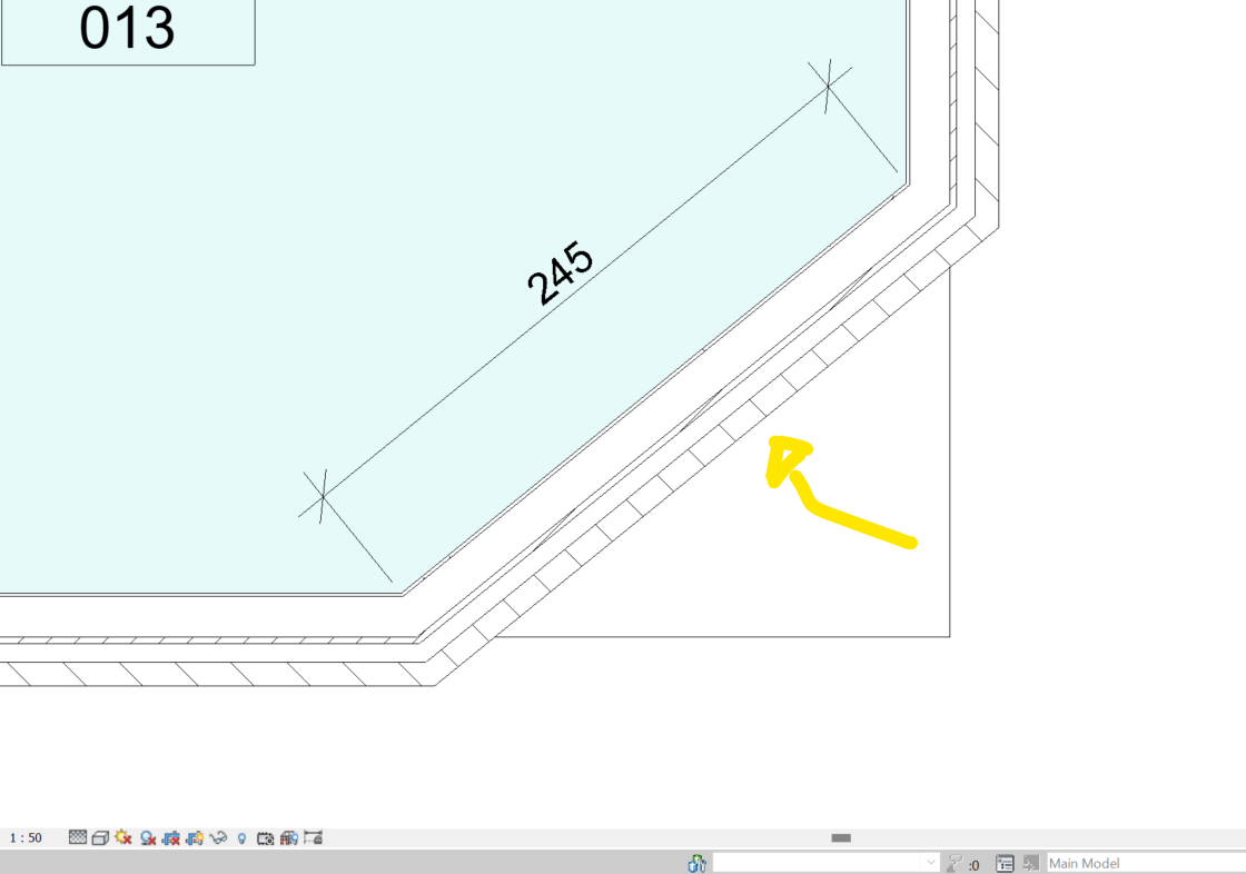
Question: I am trying to get the CUT_EDGE references of a given wall using the API. At the moment I can get part of the references based on the Wall geometry. I first go to the Solids and for each edge of the solid I check if the Reference is of type CUT_EDGE. This works but does not get all the options (I see more when generating a dimension line manually in the UI of Revit).
For example, I have the wall seen in this image:

The dimension is attached to the following CUT_EDGE references:
- 3aecdde0-f1aa-42b2-a208-f740e7a17720-003f7f7f:8:CUT_EDGE/0/1
- 3aecdde0-f1aa-42b2-a208-f740e7a17720-003f7f7f:8:CUT_EDGE/1/1
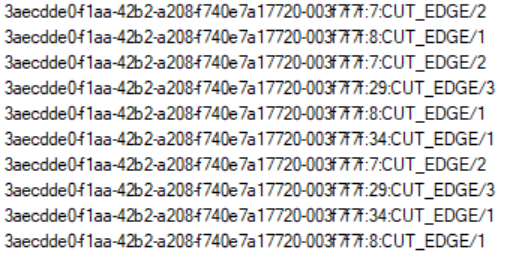
But when I run over all the edges of the wall, I only get the following options:

I tested setting visibility options, detail options, and IncludeNonVisibleObjects, but nothing helps.
I think knowing better what the structure of the stable representations mean could help a lot.
Answer: Here is my finding that actually worked, for example using the Stable Representation 3aecdde0-f1aa-42b2-a208-f740e7a17720-003f7f7f:8:CUT_EDGE/0/1.
- 3aecdde0-f1aa-42b2-a208-f740e7a17720-003f7f7f: Refers to the element itself
- 8: Is the ID of the face of the Revit
Element - CUT_EDGE/0/1: This is the type and location of the Reference. It is CUT_EDGE type, the
1means which edge of the face, and the0is its end-point index.
My original findings were correct; I was just missing the index of the end-point of the edge I found. All this is possible to find via the Edges of the Solids that are part of the geometry of an Element.
Many thanks to Joseph for his research and clear explanation!
It provides a welcome addition to The Building Coder collection of stable representation magic voodoo information:
- Reference Stable Representation Magic Voodoo
- Voodoo Magic Retrieves Global Instance Edges
- Hatch Line Dimensioning Voodoo
- Picked Instance Face Geometry in LCS Versus WCS
- Reformat Stable Representation String for Dimensioning
- Stable Reference Relationships
- Stable Representation Voodoo for Reference Intersector with Links
Revit and IFC coordinate systems
Let's round off the Revit-related topics with a short note to point out Lejla Secerbegovic' article on Revit, IFC and coordinate systems.
Chinese Influencer Deepfakes Livestreaming 24/7
Moving from the Revit API to my other favourite topic, AI et al: deepfakes of Chinese influencers are livestreaming 24/7:
With just a few minutes of sample video and $1,000 in costs, brands can clone a human streamer to work 24/7.
Generative AI Use and Misuse
Closing with another AI-related topic, an experiment reveals how people can make use of generative AI, but also misuse it, and thus how people can create – and destroy – value with generative AI:
Key Takeaways – A first-of-its-kind scientific experiment finds that people mistrust generative AI in areas where it can contribute tremendous value and trust it too much where the technology isn’t competent:
- Around 90% of participants improved their performance when using GenAI for creative ideation. People did best when they did not attempt to edit GPT-4’s output.
- When working on business problem solving, a task outside the tool’s current competence, many participants took GPT-4's misleading output at face value. Their performance was 23% worse than those who didn’t use the tool at all.
- Adopting generative AI is a massive change management effort. The job of the leader is to help people use the new technology in the right way, for the right tasks and to continually adjust and adapt in the face of GenAI’s ever-expanding frontier.