Pyramid Builder, CommandLoader, et al
Happy St. Valentine's Day!
Lots of activity in the Revit API discussion forum and elsewhere:
- Dynamic load, compile and run code
- DirectShape pyramids
- Modify level element X and Y extents
- How to filter for subsets of elements
- Switch document display units
- Material tags displaying '?'
- Sublime Text
Dynamic Load, Compile and Run Code
Recently, several Revit API discussion forum threads revolved around how to dynamically load and compile Revit add-ins.
Luiz Henrique @ricaun Cassettari now shared a solution for that,
RevitAddin.CommandLoader – compile and run IExternalCommand with Revit open:
I present my first Revit add-in open-source project CommandLoader.
With this plugin is possible to compile IExternalCommand directly in Revit, and the command is added as a PushButton in the Addins Tab.
Here is an 8-minute video explaining the features and some limitations, compile and run 'IExternalCommand' with Revit open:
RevitAddin.CommandLoader project compiles IExternalCommand with Revit open using CodeDom.Compiler and creates a PushButton on the Revit ribbon.
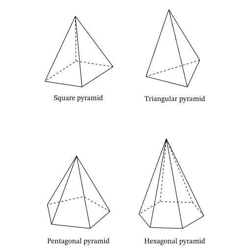
DirectShape Pyramids
Richard RPThomas108 Thomas
implemented a very nice little sample using the TessellatedShapeBuilder to create DirectShape
regular pyramids to answer
the question is it possible to create a solid from the edges of pyramids?

Answer: Yes.
You can do so with TessellatedShapeBuilder, but you only need the points, not the edges:
  Private Function Obj_230204a( _
    ByVal commandData As Autodesk.Revit.UI.ExternalCommandData,
    ByRef message As String,
    ByVal elements As Autodesk.Revit.DB.ElementSet) As Result

    Dim UIApp As UIApplication = commandData.Application
    Dim UIDoc As UIDocument = commandData.Application.ActiveUIDocument
    If UIDoc Is Nothing Then Return Result.Cancelled Else
    Dim IntDoc As Document = UIDoc.Document

    Const NumberOfSides As Integer = 6
    Const BaseRadius As Double = 1
    Const ApexHeight As Double = 2

    Dim Seg As Double = 2.0 / NumberOfSides
    Dim Points As XYZ() = New XYZ(NumberOfSides - 1) {}
    For i = 0 To NumberOfSides - 1
      Dim P As Double = i * Seg
      Dim X As Double = Math.Sin(Math.PI * P) * BaseRadius
      Dim Y As Double = Math.Cos(Math.PI * P) * BaseRadius

      Points(i) = New XYZ(X, Y, 0)
    Next
    Dim builder As New TessellatedShapeBuilder()
    builder.OpenConnectedFaceSet(True)

    'The bottom face
    builder.AddFace(New TessellatedFace(Points, ElementId.InvalidElementId))

    'Side faces
    Dim ApexPt As New XYZ(0, 0, ApexHeight)

    For i = 0 To Points.Length - 1
      Dim J As Integer = i + 1
      If i = Points.Length - 1 Then
        J = 0
      End If

      Dim P1 As XYZ = Points(i)
      Dim P2 As XYZ = Points(J)
      builder.AddFace(New TessellatedFace(New XYZ(2) {P1, P2, ApexPt}, ElementId.InvalidElementId))
    Next
    builder.CloseConnectedFaceSet()

    builder.Target = TessellatedShapeBuilderTarget.Solid
    builder.Fallback = TessellatedShapeBuilderFallback.Abort
    builder.Build()

    Dim Res As TessellatedShapeBuilderResult = builder.GetBuildResult
    If Res.Outcome = TessellatedShapeBuilderOutcome.Solid Then

      Using Tx As New Transaction(IntDoc, "Pyramid")
        If Tx.Start = TransactionStatus.Started Then

          Dim ds As DirectShape = DirectShape.CreateElement(IntDoc, New ElementId(BuiltInCategory.OST_GenericModel))
          ds.SetShape(Res.GetGeometricalObjects())

          Tx.Commit()
        End If
      End Using

    End If

    Return Result.Succeeded
  End Function
Rough C# translation from VB.NET:
  public Result Obj_230204a(
    Autodesk.Revit.UI.ExternalCommandData commandData,
    ref string message,
    Autodesk.Revit.DB.ElementSet elements)
  {
    UIApplication UIApp = commandData.Application;
    UIDocument UIDoc = commandData.Application.ActiveUIDocument;
    if (UIDoc == null)
      return Result.Cancelled;
    Document IntDoc = UIDoc.Document;

    const int NumberOfSides = 6;
    const double BaseRadius = 1;
    const double ApexHeight = 2;

    double Seg = 2.0 / NumberOfSides;
    XYZ[] Points = new XYZ[NumberOfSides];
    for (int i = 0; i <= NumberOfSides - 1; i++)
    {
      double P = i * Seg;
      double X = Math.Sin(Math.PI * P) * BaseRadius;
      double Y = Math.Cos(Math.PI * P) * BaseRadius;

      Points[i] = new XYZ(X, Y, 0);
    }
    TessellatedShapeBuilder builder = new TessellatedShapeBuilder();
    builder.OpenConnectedFaceSet(true);

    //The bottom face
    builder.AddFace(new TessellatedFace(Points, ElementId.InvalidElementId));

    //Side faces
    XYZ ApexPt = new XYZ(0, 0, ApexHeight);

    for (int i = 0; i <= Points.Length - 1; i++)
    {
      int J = i + 1;
      if (i == Points.Length - 1)
      {
        J = 0;
      }

      XYZ P1 = Points[i];
      XYZ P2 = Points[J];
      builder.AddFace(new TessellatedFace(new XYZ[3] {
      P1,
      P2,
      ApexPt
    }, ElementId.InvalidElementId));
    }
    builder.CloseConnectedFaceSet();

    builder.Target = TessellatedShapeBuilderTarget.Solid;
    builder.Fallback = TessellatedShapeBuilderFallback.Abort;
    builder.Build();

    TessellatedShapeBuilderResult Res = builder.GetBuildResult();

    if (Res.Outcome == TessellatedShapeBuilderOutcome.Solid)
    {
      using (Transaction Tx = new Transaction(IntDoc, "Pyramid"))
      {

        if (Tx.Start() == TransactionStatus.Started)
        {
          DirectShape ds = DirectShape.CreateElement(IntDoc,
            new ElementId(BuiltInCategory.OST_GenericModel));
          ds.SetShape(Res.GetGeometricalObjects());

          Tx.Commit();
        }
      }
    }
    return Result.Succeeded;
  }
Many thanks to Richard for the nice sample!
Modify Level Element X and Y Extents
Richard also suggested how to modify level extents in X and Y direction:
Question: I can get levels extents with get_BoundingBox and am looking for something like set_BoundingBox. I want to keep the level's Z elevation at the same level and stretch its bounding box in X and Y direction:

Answer: There is some functionality on the DatumPlane class that Level inherits from, e.g.:
- DatumPlane.SetCurveInView
- DatumPlane.Maximize3DExtent
- DatumPlane.PropagateToViews
Seems better to maximize the extents and propagate to views rather than individually manipulating curves.
How to Filter for Subsets of Elements
Some very basic hints on generic filtering came up in this question:
Question: ... on the parsed element structure of the Revit model; you could think of it as the model tree in Navisworks. Users want to access the parsed structured data and graphic elements of the BIM, select objects by filtering Revit views, grids, family categories or MEP systems, and then create assemblies after selecting elements for documentation.
Example 1: a relatively complex building includes multiple piping systems. The user needs to quickly select the circuit of a certain piping system on a certain floor.
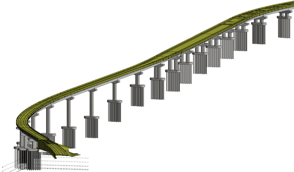
Example 2: in a section of linear engineering, such as an elevated road, the user needs to quickly select the elements between two grids:

Answer: The Revit API provides many ways to filter down to the elements you are looking for.
It depends on the particular need.
In Example 1, you might want to start with the elements in the target system, but then filter further with an ElementParameterFilter for the reference level and/or with a geometric filter like BoundingBoxIntersectsFilter or ElementIntersectsSolidFilter.
Example 2 seems more geometric, so filter first by certain categories and then use the geometric filters after calculating a shape that represents the space between grids.
For more information on all the filters, please refer to the knowledgebase article
on Applying Filters.
Switch Document Display Units
In the thread on converting all parameter values from imperial to metric units, nikolaEXEZM shared two simple macros showing how to switch document display units between Imperial and Metric.
Works with both project and family documents. Just create a new Macro Module, and paste in the code below:
public void ChangeUnitsToImperial()
{
  Document doc = this.ActiveUIDocument.Document;

  Document templateDoc = Application.OpenDocumentFile(
    @"C:\ProgramData\Autodesk\RVT "
      + this.Application.VersionNumber
      + @"\Templates\English-Imperial\default.rte");

  using (Transaction ta = new Transaction(doc))
  {
    ta.Start("Change Project Units to Imperial");
    doc.SetUnits(templateDoc.GetUnits());
    ta.Commit();
  }
}

public void ChangeUnitsToMetric()
{
  Document doc = this.ActiveUIDocument.Document;

  Document templateDoc = Application.OpenDocumentFile(
    @"C:\ProgramData\Autodesk\RVT "
      + this.Application.VersionNumber
      + @"\Templates\English\DefaultMetric.rte");

  using (Transaction ta = new Transaction(doc))
  {
    ta.Start("Change Project Units to Metric");
    doc.SetUnits(templateDoc.GetUnits());
    ta.Commit();
  }
}
Many thanks to Nikola for sharing these.
Material Tags Displaying '?'
A couple of threads mentioned a problem with material tags displaying question marks '?' after minor changes to the model, forcing the user to waste time regenerating or nudging all material tags every time right before printing a drawing set. A workaround for this was mentioned in the ticket REVIT-20249:
Standard Operating Procedure around here is right before printing, select a material tag > right click > select all instances in entire project > nudge right > nudge left > print.
Sublime Text
Closing with a non-Revit topic, I recently updated my computer to the MacBook Pro M1 ARM. Then, I updated the OS to MacOS Ventura, and my beloved and trusty old Komodo Edit text editor stopped working. It has not been maintained for years. Searching for a new minimalist text editor, I happened upon Sublime Text and started using that. I am glad to report that it works perfectly for me.
I love the way that all settings are stored in JSON and take effect the moment you save the JSON file.
Today, I also added my first own key binding, also saved in JSON and taking immediate effect on saving the file.
Now, to round it off, I installed my first plugin, implemented in Python by Giampaolo Rodola: Sublime Text: remember cursor position plugin. Same procedure: install the Python file in the appropriate location – ~/Library/Application Support/Sublime Text/Packages/User, in my case – and it immediately starts working.
I wish everything worked like this.