Aligning Connectors
A nice little C++ sample demonstrating how to align connectors, an impressive modern platform for implementing and streamlining online API processes, and my impressions of Harari's book on the history of mankind:
- Align connectors in C++
- Pipedream serverless API workflow
- Harari: Sapiens
- Afterword: The Animal that Became a God
By the way, The Building Coder was selected by feedspot as one of the Top 10 Dynamo Blogs. Thank you for the recognition.
Align Connectors
Haluk Uzuner raised and solved the interesting issue of how to align connectors in 3D space, sharing his C++ implementation:
Question: I want to align two families by their connectors.
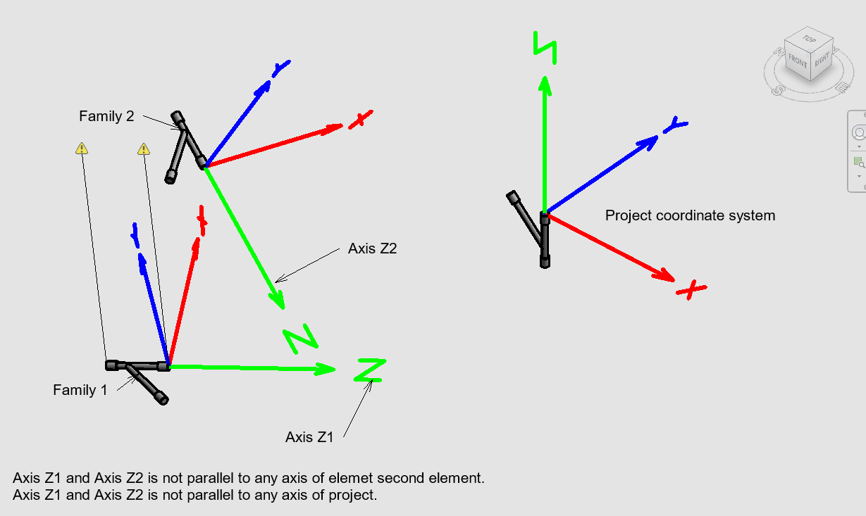
Families can be placed in any direction in 3D space. Any axis of any element is not to parallel to each other and project coordinates. Graphically, it might look like this:
 <! 1229 x 733 -->
My code is below. It works when the element is located parallel to project axes, but not in the general situation.
Am I in the wrong path? Is there a better way to do it?
private: static void rotate(UIApplication^ uiapp, elmstoreplace^ elms)
{
  // Select some elements in Revit before invoking this command

  // Get the handle of current document.
  UIDocument^ uidoc = uiapp->ActiveUIDocument;
  Document^ doc = uidoc->Document;

  // Elelements are stored in other header. We will read from there.
  // We saved them there by selecting in GUI.
  Element^ elmfrom = doc->GetElement(elmstoreplace::elmFrom); // Element will be aligned.
  Element^ elmto = doc->GetElement(elmstoreplace::elmTo); // Element will be aligned to.

  // 1. Cast Element to FamilyInstance
  FamilyInstance^ faminstfrom = (FamilyInstance^)elmfrom;
  FamilyInstance^ faminstto = (FamilyInstance^)elmto;

  // 2. Get MEPModel Property
  MEPModel^ mepmodelfrom = faminstfrom->MEPModel;
  MEPModel^ mepmodelto = faminstto->MEPModel;

  // 3. Get connector set of MEPModel
  ConnectorSet^ connectorSetfrom = mepmodelfrom->ConnectorManager->Connectors;
  ConnectorSet^ connectorSetto = mepmodelto->ConnectorManager->Connectors;

  // Connector numbers to be aligned to each other are stored in other file.
  // We saved them there by selecting in GUI.
  Connector^ connFrom =nullptr; // Connector will be aligned.
  Connector^ connTo = nullptr; // Connector to be aligned to.

  // Get connector by iterating in connectorset.
  for each (Connector ^ connector in connectorSetfrom)
  {
    if (connector->Id == elmstoreplace::connNoFrom)
    {
    connFrom = connector;
    }
  }

  // Get connector by iterating in connectorset.
  for each (Connector ^ connector in connectorSetto)
  {
    if (connector->Id == elmstoreplace::connNoTo)
    {
     connTo = connector;
    }
  }

  // Get the element current location
  LocationPoint^ elmfromLoc = (LocationPoint^)elmfrom->Location;

  // Create vector based on element location and connector location.
  XYZ^ diffvec1 = connFrom->Origin->Subtract(elmfromLoc->Point);
  // Subtract element location which will be moved.
  XYZ^ diffvec2 = connTo->Origin->Subtract(elmfromLoc->Point);
  // Bring two connectors to same point
  ElementTransformUtils::MoveElement(doc, elmfrom->Id, diffvec2->Add(diffvec1->Negate()));

  // Get basisZ of connectors.
  XYZ^ basisZTo = connTo->CoordinateSystem->BasisZ;
  // Transform vector.
  XYZ^ getOfbasisZTo = getOfVector(basisZTo);
  // Get basisZ of connectors.
  XYZ^ basisZFrom = connFrom->CoordinateSystem->BasisZ;
  // Transform vector.
  XYZ^ getOfbasisZFrom = getOfVector(basisZFrom);

  // Calculate angle between connectors.
  double angle  = getOfbasisZTo->AngleTo(getOfbasisZFrom);

  // Calculate crossproduct of two vectors.
  XYZ^ crossprod = getOfbasisZTo->CrossProduct(getOfbasisZFrom);
  // Calculate crossproduct of two vectors.
  // Somehow this always give unit vectors
  // BasisX(1,0,0), BasisY(0,1,0), BasisX(0,0,1)
  // I think that is my problem.
  XYZ^ getOfcrossprod = getOfVector(crossprod);

  // Create rotation axis.
  Line^ rotationaxis = Line::CreateUnbound(connTo->Origin, crossprod->BasisZ);

  // Rotate element around axis.
  ElementTransformUtils::RotateElement(doc, elmfrom->Id, rotationaxis, Math::PI - angle);
}

public: static XYZ^ getOfVector(XYZ^ xyz)
{
  XYZ^ OfVector(xyz);
  return xyz;
}
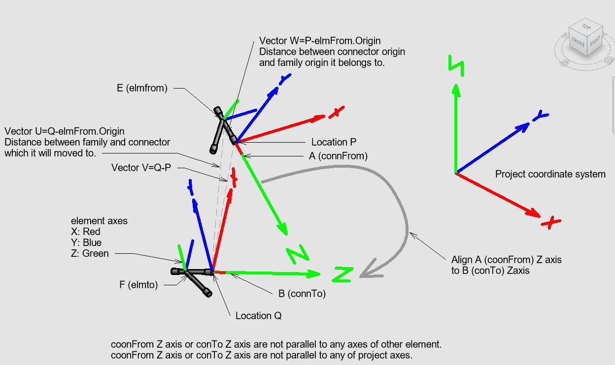
Answer: To align the connectors, given two elements E and F containing connectors A and B with locations P and Q:
Determine the difference between P and Q, the vector V = Q - P. If you translate the element E containing A by V, A will lie in exactly the same spot as B. If you don't want it in the exact same spot, but only vertically or horizontally aligned in some way, you need to adapt some of the coordinates of V accordingly. The translation can be accomplished using the MoveElement method. Watch out that other attached elements are not moved as well.
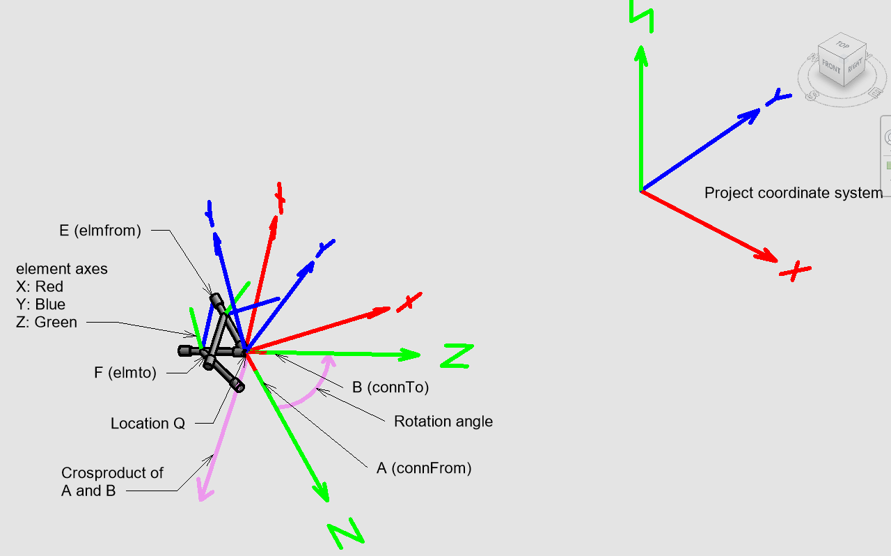
Response: I added some improved pictures below. As far as understood, move element moves families/elements only. So, I find U vector and subtract P from it and find the V vector you mentioned. In the way you mentioned, it works if two families placed in the same plane and orientation. In my case, none of axes are parallel. My problem starts after moving element. My aim is finding cross product of two Z axes that is perpendicular to both axes. And rotate it by angle. I am stuck in creating a rotation axis along Z axis of cross product. As shown in the picture, cross product BasisX, Y, Z always give unit vectors.


Later:
I finally got it to work.
My problem was understanding the Basis vectors.
My final code is below.
It worked perfectly for me.
I additionally draw rotation axis and rotation arc to visualize rotation.
Besides, I was surprised there are no similar code samples on the Internet. There are many samples, but they all work on parallel planes. Revit itself already does the action which I am after. But apparently, API developers didn't need it.
private: static void RotateOnConnector(UIApplication^ uiapp, elmstoreplace^ elms)
{
  try
  {
    // Select some elements in Revit before invoking this command

    // Get the handle of current document.
    UIDocument^ uidoc = uiapp->ActiveUIDocument;
    Document^ doc = uidoc->Document;

    // Elelements are stored in other header. They will be read from there.
    // They are saved there by selecting in GUI.
    Element^ elmfrom = doc->GetElement(elmstoreplace::elmFrom);
    Element^ elmto = doc->GetElement(elmstoreplace::elmTo);

    // 1. Cast Element to FamilyInstance
    FamilyInstance^ faminstfrom = (FamilyInstance^)elmfrom;
    FamilyInstance^ faminstto = (FamilyInstance^)elmto;

    // 2. Get MEPModel Property
    MEPModel^ mepmodelfrom = faminstfrom->MEPModel;
    MEPModel^ mepmodelto = faminstto->MEPModel;

    // 3. Get connector set of MEPModel
    ConnectorSet^ connectorSetfrom = mepmodelfrom->ConnectorManager->Connectors;
    ConnectorSet^ connectorSetto = mepmodelto->ConnectorManager->Connectors;

    // Connector numbers to be aligned to each other are stored in other file.
    // They saved there by selecting in GUI.
    Connector^ connFrom =nullptr; // Connector will be aligned.
    Connector^ connTo = nullptr; // Connector to be aligned to.

    // Get connector by iterating in connectorset.
    for each (Connector ^ connector in connectorSetfrom)
    {
      if (connector->Id == elmstoreplace::connNoFrom)
      {
        connFrom = connector;
        String^ message = "Connector is owned by: " + connector->Owner->Name;
      }
    }

    // Get connector by iterating in connectorset.
    for each (Connector ^ connector in connectorSetto)
    {
      if (connector->Id == elmstoreplace::connNoTo)
      {
        connTo = connector;
      }
    }

    // Get the element current location
    LocationPoint^ elmfromLoc = (LocationPoint^)elmfrom->Location;

    // Create vector based on element location and connector location.
    XYZ^ diffvec1 = connFrom->Origin->Subtract(elmfromLoc->Point);
    // Subtract element location which will be moved.
    XYZ^ diffvec2 = connTo->Origin->Subtract(elmfromLoc->Point);
    // Bring two connectors to same point
    ElementTransformUtils::MoveElement(doc, elmfrom->Id, diffvec2->Add(diffvec1->Negate()));

    // Get BasisZ of connectors.
    XYZ^ basisZTo = connTo->CoordinateSystem->BasisZ;
    XYZ^ basisZFrom = connFrom->CoordinateSystem->BasisZ;

    // Calculate angle between connectors.
    double angle  = basisZTo->AngleTo(basisZFrom);

    // Calculate cross product of two vectors.
    XYZ^ crossprod = basisZTo->CrossProduct(basisZFrom);

    // Create rotation axis.
    Line^ rotationaxis = Line::CreateBound(connTo->Origin,
      gcnew XYZ(connTo->Origin->X+crossprod->X,
      connTo->Origin->Y+crossprod->Y,
      connTo->Origin->Z+crossprod->Z));

    // Rotate element around axis.
    ElementTransformUtils::RotateElement(doc, elmfrom->Id,
      rotationaxis, Math::PI-angle);

    // get handle to application from document
    Autodesk::Revit::ApplicationServices::Application^ application
      = doc->Application;

    // Create a geometry line in Revit application
    XYZ^ startPoint = connTo->Origin;
    XYZ^ endPoint = gcnew XYZ(connTo->Origin->X + crossprod->X,
     connTo->Origin->Y + crossprod->Y,
     connTo->Origin->Z + crossprod->Z);
    Line^ geomLine = Line::CreateBound(startPoint, endPoint);

    // Create a geometry plane in Revit application
    Plane^ linePlane = Plane::CreateByThreePoints(
    connTo->Origin,
    gcnew XYZ(connTo->Origin->X,
    connTo->Origin->Y,
    connTo->Origin->Z + connTo->CoordinateSystem->BasisZ->Z),
    gcnew XYZ(connTo->Origin->X + crossprod->X,
    connTo->Origin->Y + crossprod->Y,
    connTo->Origin->Z + crossprod->Z));
    Plane^ arcPlane = Plane::CreateByNormalAndOrigin(crossprod->Normalize(),
      connTo->Origin);
    Arc^ geomArc = Arc::Create(arcPlane, 0.5, 0, angle);

    // Create a sketch plane in current document
    SketchPlane^ linesketch = SketchPlane::Create(doc, linePlane);
    SketchPlane^ arcsketch = SketchPlane::Create(doc, arcPlane);

    // Create a ModelLine element using the created geometry line and sketch plane
    ModelLine^ line = (ModelLine^)doc->Create->NewModelCurve(geomLine, linesketch);

    // Create a ModelArc element using the created geometry arc and sketch plane
    ModelArc^ arc = (ModelArc^)doc->Create->NewModelCurve(geomArc, arcsketch);
  }
  catch (Exception^ ex)
  {
    TaskDialog::Show("!!! ", ex->Message->ToString());
  }
}
Many thanks to Haluk for rectifying that and sharing this nice topic and C++ solution.
Pipedream Serverless API Workflow
Pipedream is a fast way to automate any process that connects APIs. Build and run workflows with code-level control when you need it, and no code when you don't.
The Pipedream platform includes:
- A serverless runtime and workflow service
- Open source triggers and actions for hundreds of integrated apps
- One-click OAuth and key-based authentication for hundreds of APIs
Check out the impressive 7-minute demo using:
- Pre-built, open source components for Twitter and Google Sheets
- Node.js with the axios npm package and Pipedream managed authentication for Google Translate
- Python and the nltk pypi package
Harari: Sapiens
I read Sapiens: A Brief History of Humankind by Yuval Noah Harari.
Judging from the very critical scholarly reception of the book, I must be naive to enjoy it so much.
Judging from the enthusiastic popular reception, though, I guess I am average after all.
Afterword: The Animal that Became a God
SEVENTY THOUSAND YEARS AGO, HOMO sapiens was still an insignificant animal minding its own business in a corner of Africa. In the following millennia it transformed itself into the master of the entire planet and the terror of the ecosystem. Today it stands on the verge of becoming a god, poised to acquire not only eternal youth, but also the divine abilities of creation and destruction.
Unfortunately, the Sapiens regime on earth has so far produced little that we can be proud of. We have mastered our surroundings, increased food production, built cities, established empires and created far-flung trade networks. But did we decrease the amount of suffering in the world? Time and again, massive increases in human power did not necessarily improve the well-being of individual Sapiens, and usually caused immense misery to other animals.
In the last few decades we have at last made some real progress as far as the human condition is concerned, with the reduction of famine, plague and war. Yet the situation of other animals is deteriorating more rapidly than ever before, and the improvement in the lot of humanity is too recent and fragile to be certain of.
Moreover, despite the astonishing things that humans are capable of doing, we remain unsure of our goals and we seem to be as discontented as ever. We have advanced from canoes to galleys to steamships to space shuttles – but nobody knows where we’re going. We are more powerful than ever before, but have very little idea what to do with all that power. Worse still, humans seem to be more irresponsible than ever. Self-made gods with only the laws of physics to keep us company, we are accountable to no one. We are consequently wreaking havoc on our fellow animals and on the surrounding ecosystem, seeking little more than our own comfort and amusement, yet never finding satisfaction.
Is there anything more dangerous than dissatisfied and irresponsible gods who don’t know what they want?
– Published online by Erenow