Boundary Elements and Stirrup Constraints
I had a lengthy and fruitful conversation on implementing valid stirrup constraints, and several experienced developers added more advice on determining boundary elements for the entire building and individual rooms:
- Rebar stirrup constraints
- Jason and Matt on bounding elements
- Revit API and UX style guide
- Today's collective action problem
Rebar Stirrup Constraints
Summarising a nice conversation leading to a satisfactory conclusion in the Revit API discussion forum thread on problem with constraining stirrups to the cover of the host element:
Question: I have been working on an add-in to automatically place stirrups inside a host element (Structural Column, in this case).
I use the Rebar.CreateFromRebarShape method in order to create the stirrup inside the column.
However, the RebarShape came with its own dimensions and thus didn't fit inside the concrete cover.
Through the Revit user interface, every time the stirrup is placed manually inside a host element in the plan view, Revit can automatically constrain the stirrup edges to be inside the cover.
How to do the same thing through the Revit API?
I have tried getting the RebarConstraintManager of the newly created stirrup, iterating through all of its handles and changing the preferred RebarConstraint to ToCover as illustrated in the code snippet shown below:
  Rebar stirrup = Rebar.CreateFromRebarShape( doc,
    rebarShape, barType, column, bottomLeftXYZ1,
    XYZ.BasisX, XYZ.BasisY );

  // Modify the RebarConstraint
  RebarConstraintsManager rebarConstraintsManager
    = stirrup.GetRebarConstraintsManager();

  IList<RebarConstrainedHandle> rebarConstrainedHandles
    = rebarConstraintsManager.GetAllConstrainedHandles();

  foreach( RebarConstrainedHandle handle
    in rebarConstrainedHandles )
  {
    List<RebarConstraint> constraintCandidates
      = rebarConstraintsManager
        .GetConstraintCandidatesForHandle( handle )
        .ToList();

    RebarConstraint toCoverConstraint
      = constraintCandidates.Find( c
        => c.IsToCover() == true );

    RebarConstraint constraint
      = rebarConstraintsManager
        .GetCurrentConstraintOnHandle( handle );

    if( !constraint.IsToCover() )
    {
      rebarConstraintsManager
        .SetPreferredConstraintForHandle( handle,
          toCoverConstraint );
    }
  }
After running the program, nothing changed at all to the stirrup and it still didn't fit inside the concrete cover of the column host.
By debugging, I discovered that the GetAllConstrainedHandles method returns 0 handles, which is why the rest of the program didn't work.
Why did the method return zero handles even though the handles are visible in the user interface (both the dot and triangle handles)?
Are there other methods to snap the stirrup inside the concrete cover?
Answer 1: Rebar is quite a complex area of the API due to the various objects involved:
RebarShapeDrivenAccessor ScaleToBox purportedly uses the same algorithm as when you place shape in section view for example.
From this, you probably have to work out the size of the rectangle by looking at cross section deducting covers, not sure there is a faster method. You probably have to size to get it somewhere near and then constrain (historically I've noticed similar in UI).
There is a related method RebarShapeDrivenAccessor ScaleToBoxFor3D.
RebarShapeDrivenAccessor comes from Rebar.GetShapeDrivenAccessor and is specific to shape driven rebar.
I'm not sure this algorithm always gets it right (from UI experience with it) and there is an element of rationalisation of free end dimensions that need to be applied afterwards. Perhaps sometimes it can't be placed at all, and perhaps sometimes when you increase the bar diameter the shape can't be made (after placing a smaller bar diameter size), i.e., due to the larger bending diameter reducing the distance between straights.
Response: I tried the ScaleToBox method that you suggested as shown in the code snippet below:
  Rebar stirrup = Rebar.CreateFromRebarShape(
    doc, rebarShape, barType, column, bottomLeftXYZ1,
    XYZ.BasisX, XYZ.BasisY );

  stirrup.GetShapeDrivenAccessor().ScaleToBox(
    bottomLeftXYZ1, new XYZ( horDist, 0, 0 ),
      new XYZ( 0, vertDist, 0 ) );
It seems to work well, the stirrup indeed got resized according to the rectangle that is specified by the ScaleToBox() method, I will double check whether all the parameters are correct after the scaling.
Answer 2: You should use:
public IList<RebarConstrainedHandle> GetAllHandles();
That returns all RebarConstrainedHandles of this bar.
All RebarConstrainedHandle objects will be returned, regardless of whether there are constraints associated to them.
The GetAllConstrainedHandles function returns all handles that are already constrained to external references.
Response: I tried the method that the development team suggested and indeed it works! I can now get the handles in the rebar. However, after setting a new RebarConstraint to each handle in order to snap them to the concrete cover of the host element, the stirrup didn't change to be inside the cover.
Let me provide more details to my case.
In the beginning, I tried to create a stirrup inside the column by using CreateFromRebarShape like this:
  Rebar stirrup = Rebar.CreateFromRebarShape( doc,
    rebarShape, barType, column, bottomLeftXYZ1,
    XYZ.BasisX, XYZ.BasisY );
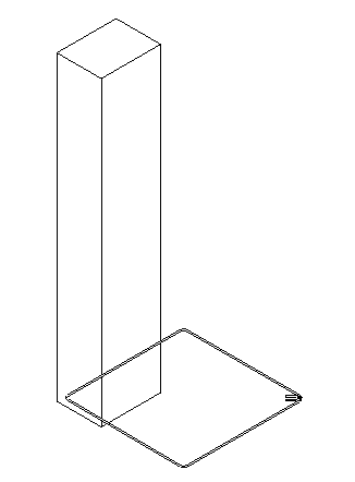
I used the default RebarShape called T1 which is provided as a template by Revit, and the result of the above code is a stirrup. However, the sizes of the stirrup don't match my current column (each rebar shape should have their own default dimensions) as shown below:
That is why I am trying to fit the stirrup inside my column as what the Revit can do through the user interface as shown below:
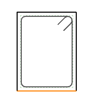
Placing a stirrup through the user interface (the selected rebar shape T1 automatically got constrained inside the cover)
I fixed my C# code to the following based on your suggestion in order to change the RebarConstraints to be inside the cover:
  Rebar stirrup = Rebar.CreateFromRebarShape( doc,
    rebarShape, barType, column, bottomLeftXYZ1,
    XYZ.BasisX, XYZ.BasisY );

  #region // Modify the RebarConstraint
  // (Trying to snap the stirrup to the rebar)
  RebarConstraintsManager rebarConstraintsManager
    = stirrup.GetRebarConstraintsManager();

  IList<RebarConstrainedHandle> rebarConstrainedHandles
    = rebarConstraintsManager.GetAllHandles();

  foreach( RebarConstrainedHandle handle in rebarConstrainedHandles )
  {
    List<RebarConstraint> constraintCandidates
      = rebarConstraintsManager
        .GetConstraintCandidatesForHandle( handle ).ToList();

    RebarConstraint toCoverConstraint = constraintCandidates.Find(
      c => c.IsToCover() == true );
    RebarConstraint constraint = rebarConstraintsManager
      .GetCurrentConstraintOnHandle( handle );

    if( constraint == null || !constraint.IsToCover() )
    {
      rebarConstraintsManager.SetPreferredConstraintForHandle(
        handle, toCoverConstraint );
    }
  }
Indeed, the RebarConstraint did change to be constrained to the cover as shown in the following images:
Before implementing the code (the handles are constrained to the Host face as shown by the orange line at the host face):
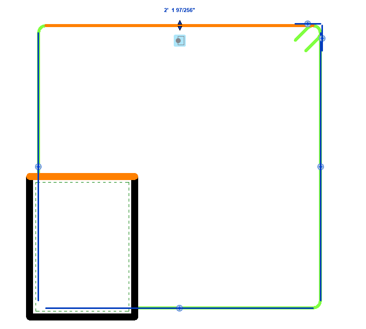
Before implementing the code (the handles are constrained to the host face)
After implementing the code (the handles are now constrained to the cover as shown by the blue logo under the triangle handles):
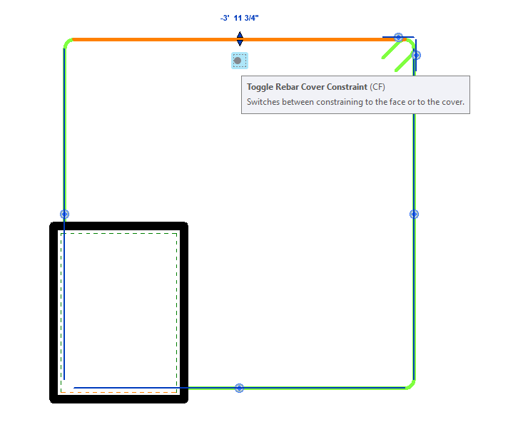
After implementing the code snippet (the handles are indeed constrained to the cover as shown by the blue toggle rebar cover constraint logo)
Even though the stirrup indeed got constrained to the cover, but it didn't automatically resize just like in the user interface. Any suggestion on how I can achieve similar result as through the user interface?
Answer: You should set the distance between bar segment and the cover to zero, i.e., constraint.SetDistanceToTargetCover(0.0).
Another thing I observe in the last picture: the highlighted segment is constrained to the bottom cover; however, it should be constrained to the upper one.
In this case, for each segment, there are two constraint candidates that are to cover.
You should choose the one that is closer to the segment.
constraint.GetDistanceToTargetCover can be used to obtain the distance between bar segment and the cover candidate.
Response: I believe I am pretty close in cracking the case down. I implemented the suggestions into the following code snippet:
  Rebar stirrup = Rebar.CreateFromRebarShape( doc,
    rebarShape, barType, column, bottomLeftXYZ1,
    XYZ.BasisX, XYZ.BasisY );

  RebarConstraintsManager rebarConstraintsManager
    = stirrup.GetRebarConstraintsManager();

  IList<RebarConstrainedHandle> rebarConstrainedHandles
    = rebarConstraintsManager.GetAllHandles();

  foreach( RebarConstrainedHandle handle
    in rebarConstrainedHandles )
  {
    List<RebarConstraint> constraintCandidates
      = rebarConstraintsManager
        .GetConstraintCandidatesForHandle( handle ).ToList();

    List<RebarConstraint> toCoverConstraints
      = constraintCandidates.FindAll( c
        => c.IsToCover() == true );

    // Find the nearest cover constraint to the handle

    // Temporarily set the variable to
    // the first RebarConstraint element

    RebarConstraint nearestToCoverConstraint
      = toCoverConstraints[ 0 ];

    // Loop through the RebarConstraint list to find
    // the nearest cover constraint

    foreach( RebarConstraint constraint
      in toCoverConstraints )
    {
      if( constraint.GetDistanceToTargetCover()
        < nearestToCoverConstraint.GetDistanceToTargetCover() )
      {
        nearestToCoverConstraint = constraint;
      }
    }

    // Setting distance of the handle to the Host cover

    nearestToCoverConstraint.SetDistanceToTargetCover( 0.0 );

    // Setting the RebarConstraint as the
    // preferred constraint to the handle

    RebarConstraint currentConstraint
      = rebarConstraintsManager.GetCurrentConstraintOnHandle(
        handle );

    if( currentConstraint == null
      || !currentConstraint.IsToCover() )
    {
      rebarConstraintsManager.SetPreferredConstraintForHandle(
        handle, nearestToCoverConstraint );
    }
    RebarConstraint constraintTest = rebarConstraintsManager
      .GetPreferredConstraintOnHandle( handle );
  }
Compared to the previous code snippet, I now store all of the possible ToCover constraints inside the toCoverConstraints List, and precisely as you have mentioned, there are 2 possible ToCover constraints detected and I need to find the closest one to the handle.
I then implemented the GetDistanceToTargetCover method as you suggested in order to find the constraint that is closest to the handle.
Afterwards, I set the distance to 0 and then I set the modified constraint to the handle.
However, an error occurred (Rebar Shape Failure) inside Revit when running the add-in:
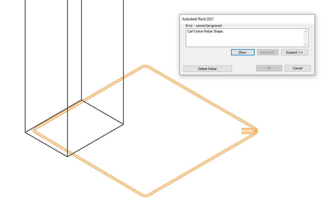
First thing that I did trying to solve this issue was checking the Handle Types of each of the Rebar handles obtained from RebarConstraintsManager GetAllHandles.
There are 7 Handles in total, 1 handle has the RebarHandleType of RebarPlane, 4 handles have the RebarHandleType of Edge, the last two Handles are of the type StartOfBar and EndOfBar respectively.
I tried setting the ToCover constraint only to specific handle types (to Edge type only, to StartOfBar and EndOfBar handles only, etc) but the same Rebar Shape Failure still appear.
If I try to model the stirrups manually using the Revit User Interface (using the same Rebar Shape that I used in the Add-in) and then checking each of the Rebar Constraint, I got the following set up in the User Interface:
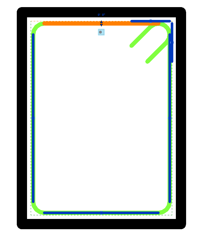
One of the Edge handle, constrained to cover at zero distance
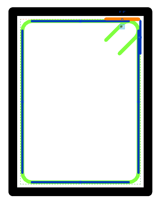
StartOfBar handle, constrained to cover at zero distance
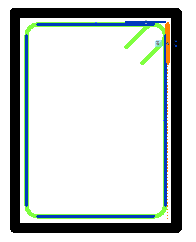
EndOfBar handle, constrained to cover at zero distance
Looking at these handle constraints of the manually created stirrups in the User Interface, they are all constrained to Cover, and have their distance set at zero. The suggestions you provided should lead to the correct approach (The code snippet already implemented approaches to find the correct cover and then setting the distance to zero). However, I still couldn't get the same result as the stirrup created through the User Interface. Instead, I am getting the Rebar Shape Failure Error that forces me to delete the rebar. Is there something that I am missing here that I am still unaware of?
Answer: It looks like the constraints that were set were not good. You should debug more to understand what is happening. For example, the API can set the constraints but without setting the distance zero to cover. Then, look in Edit Constraints and check if each handle is constrained to the expected cover. Here, I'm expecting to see that the constraints were not set to the correct cover and should be investigated.
More can be done. Create the bar without setting any constraints from API: from Revit UI, Edit Constraints, go and set constrains manually for each segment. Then, with an API command, for each constraint, set the distance to 0. There should be no error. I'm expecting this to work without any problems.
To debug it, you need the sample model and the entire code, not just the part with constraints, but also the code that calculates the rebar curves.
Response: Once again, thank you so much for taking your time in answering my queries.
You are right!
After debugging in the manner suggested, I found out that the handles are constrained to the wrong side of the Rebar Cover, thus setting the distance to zero will result in an error.
After checking my code again, I figured out that RebarConstraint `GetDistanceToTargetCover will return distance with the plus/minus sign.
Thus, in order to find the nearest constraint to the cover, I need to compare the absolute value.
In the end, I can successfully get the correct result!
Thank you.
Jason and Matt on Bounding Elements
Jason @mastjaso Masters very kindly jumped in with some experienced advice on exterior walls and room bounding elements in the Revit API discussion forum thread on how to get the walls, ceiling and floor of a room, saying:
I've been down this road before and it depends on what precisely you're trying to do with the walls, and whether you need interior walls etc.
Just Exterior Bounding Walls
If you just need the exterior walls of the room, then the simplest method is to use
the GetBoundarySegments method.
Every room, space, and area in Revit inherits from the SpatialElement class which has this method, and will return a list of RoomBoundarySegments, each one containing the curve segment, and what element is creating it (wall, room boundary line, etc.).
This will solve that whole wall centroid being outside of the room problem.
It's probably worth noting that this method will not work in precise situations with linked files, a bug I documented here. I haven't tested it since then, but I would be very surprised if Revit actually fixed it since, so it's worth watching out for.
All Walls Including Non-Bounding Interior Walls
Otherwise, if you need walls that are non-bounding and interior to the room, I found that, in general, all of Revit's projection methods are somewhat slow (and algorithms using them often have edge cases that might be missed), but, like others have said, I found both the BoundingBoxIntersector and the IsPointInRoom methods to be very fast and performant.
To get all of the walls associated with a room, including interior ones, I would first use the boundary segments method to get the bounding walls / walls that won't be inside the room.
Then, use the bounding box intersector filter to get all the walls in the model that intersect your room (as said, bounding boxes are rectangular and don't rotate, so this will be rough and pick up walls from other rooms).
Set aside the walls that you already know are the boundaries; then, for the rest, check the coordinates of the end point and midpoint of each wall segment to see if any of those points are in the room with the IsPointInRoom method.
If one of them is, then that wall cuts through the interior of the room.
I believe the only situation that this might miss is if you had a room that is bounded by room boundary lines, and a super long non-bounding wall cut entirely through the room without any end points or midpoints landing within the room.
Floors And Ceilings
Getting the floors and ceiling is somewhat more complicated and I believe will likely necessitate projection if you want to be able to capture every bulk head / potential split level etc.
What I would do is start with your room's bounding box.
Then, generate a grid of points with even spacing inside this box (maybe 0.5 - 1ft apart), halfway between the top and bottom. Test each point with the IsPointInRoom method and discard the ones that aren't.
You'll now have an irregular grid of points, all located within the bounds of your room.
For each point, project a ray upwards and one downwards and capture any floors or ceilings that they intersect before leaving your room bounds.
This should reliably capture every single floor and ceiling associated with a room.
If it is missing any, you can just increase the resolution of your point grid.
Matt's Approach
Matt Kincaid of Lighting Analysts adds in a comment on LinkedIn:
We've grappled with different approaches for finding exterior walls for some time.
Ultimately, settled on using the IsExterior API method.
But that relies on the user to set the function parameter properly, which isn’t always easy (e.g., if it’s in a linked model).
Will have to give this approach a try.
For getting the Room Bounding elements, we use this algorithm:
- Buffer the room footprint by offsetting the boundary by 1/16" outward (to include walls) using NetTopologySuite.
- Create a vertical extrusion using the buffered foot print using the
GeometryCreationUtilitiesAPI. Also buffered by 1/16" to include the floor and ceiling. - Use the
ElementIntersectsSolidFilterto find all elements intersecting the extrusion.
This fails if the Room can't be represented as a simple extrusion (e.g., multiple/sloped ceilings or floors). But works well for many cases. Ultimately, it would be handy if the Revit API exposed a way to just get all the room bounding elements which are constraining the room geometry. Something for Revit Ideas, perhaps.
Many thanks to Jason and Matt for their good advice and experience!
Revit API and UX Style Guide
Question: I am exploring developing Revit add-ins making use of our proprietary lighting controls expertise. I was wondering if Autodesk has a style guide for Revit add-ins, or Revit itself, that we could access to ensure consistency of the user experience?
Answer: Have you seen the Philips Lighting design app built by one of our partners, Xinaps? Web based... automates lighting selection and design and inserts directly into Revit models. If not, a YouTube search on Philips Xinaps Revit should get you there.
Style guide for Revit add-ins... Sorry, but no we don't. Best your UX people can do is plagiarize as much of the Revit look and feel as they can, possibly with some subtle additional signature effects, like subtle use of your specific brand colour.
The Revit API supports some UI functionality. Everything that you create using that official API will fit in with the standard Revit style. However, it is pretty limited, so many developers end up adding some of their own WPF and other UI on top of that. If you refrain from that, you are guaranteed style compatibility.
Response: From my (novice) vantage, there are a couple of areas that our add-in would need to integrate with:
- Ribbon definition and navigation
- Interaction with application elements: picking elements, locating objects, etc.
- Database read/write at both the project and object levels
- Specific dialogues to support our add-in
Can you suggest some reference materials which would help us better understand programming Revit?
Answer: Sure:
- Getting started with the Revit API, including the My First Revit Plug-In video tutorial
- Ribbon definition is discussed in the Revit API training labs, specifically part 2, Revit UI API
- Db read-write is included in the getting started material
- WPF or WinForms or whatever you are already using... anything that works with .NET In addition, all your questions are amply covered in the Revit API discussion forum
Today's Collective Action Problem
Mancur Olson published The Logic of Collective Action in 1965, analysing situations in which human beings motivated by individual gain behave in a destructive manner for the common good, the collective action problem, calling it a tragedy of the commons.
In 1990, in her 1990 book Governing the Commons, Elinor Ostrom named examples of communities that deal rationally with their limited shared resources. This may sound simple and banal, but was a revolutionary thought: people can maintain shared goods rationally and sustainably without privatisation or laws imposed from outside. To discover this, we must look at the local level, e.g., small towns, villages and cooperatives. For instance, locally managed forests are often better protected than state parks, since many people do not identify with the rules imposed from 'above'. Based on this, Ostrom recommends a 'polycentric' approach to deal with the climate change challenge, the greatest collective action problem of our time and maybe all times. We all need to feel our collective responsibility. We cannot just sit around and wait for a single global solution. For this insight, in 2009, Ostrom became the first woman to be honoured with a Nobel prize in economy.