Exterior Walls and Room Bounding Elements
Let's look at the outer boundaries of both buildings and rooms today; note that both of these topics are continued in the subsequent follow-up post on boundary elements:
Finding Exterior Walls Continued
We discussed some approaches to retrieve all exterior walls three years ago using different approaches:
- The built-in wall function parameter
FUNCTION_PARAM, tested by theIsExteriorAPI method - Using the
BuildingEnvelopeAnalyzerclass - Placing room separation lines outside the building envelope and creating a huge room around the entire building
Further aspects were added a week later in a second round on retrieving all exterior walls revisited.
The discussion now continued between Александр Пекшев or Alexander Pekshev of ModPlus and Lucas Moreira in a series of comments on that post:
Александр: There is one simple enough algorithm that allows you to find the exterior walls, even in an open loop. The algorithm consists of two parts:
- The main part – From the centre of the LocationCurve of the wall, two perpendicular rays (long lines) are shot on either side of the LocationCurve. Determine the number of intersections of these rays with other walls. If the number of intersections on one side is zero, this is an outer wall.
- An additional part – The first part will not find all the walls, so the second pass should check the remaining walls at the intersections with the found exterior walls: if the wall with its ends connects to the two outer walls, it means it is also external
The working capacity of this algorithm is almost ideal.
Here are the results of my algorithm:
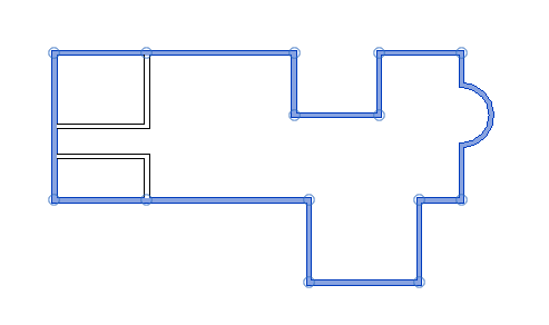
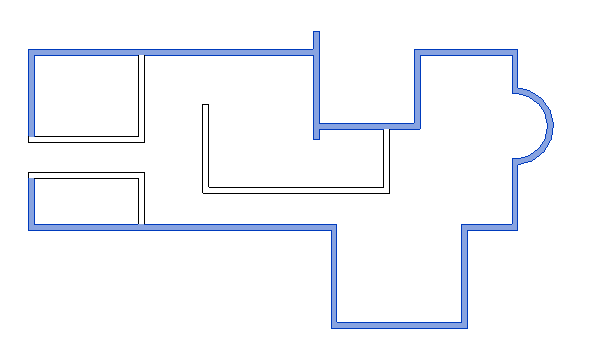
I describe the algorithm in more detail in my article on Revit: Exterior Wall Search Algorithm.
The code is provided in the RevitFindExteriorWalls GitHub repository.
Lucas: how do you solve the problem of having an interior wall that touches 2 exterior walls?
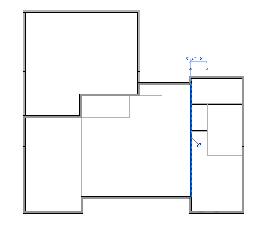
Александр: Today, I figured out the problem in your example. In this case, it is necessary to improve the second part of the check and introduce some additional checks. There will always be special cases. The screenshot shows that three walls are connected there in one place – it seems to me that this needs to be taken into account.
In the 'main part' of the algorithm, if there are intersections on both sides of the wall, then it is internal. And the connections at the ends of the wall are no longer important.
Lucas: Thanks for your response. What I did is use 3 rays at different angles from each side: 45, 90 and 135 degrees. If at least one of the rays doesn't hit anything, it's an exterior wall. This took care of the special cases I had so far. I believe shallower angles might be best. So, maybe something like (5, 90, 175) will probably yield better, more correct results. Another thing is I am not levelling the location lines. Meaning that walls have to be on the same level to intersect each other.
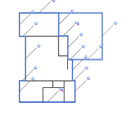
All blue walls are exterior, and the garage in the top right is on a different level of the rest.
Another approach that worked is using a convex hull to find at least one exterior wall (any location line that intersects the hull is an outermost wall). Then, from the selected exterior wall, move counterclockwise, always trying to find a right turn; this is a bit slower, but needs no special cases to work with all the projects I've tested.
Александр: Convex hull is suitable if the outer walls form a precise chain of connections. But it is not always the case. In addition, there it will be necessary to collect these very connections, which is also not an easy task (there are many nuances).
While writing the message, another idea came to mind:
- Determine the overall contour of all selected walls and find the midpoint
- Around the contour with an indent from the contour, throw the rays towards the midpoint. Throw the rays through a certain step.
The first wall that intersects with the ray is the outer one.
Interesting idea! Need to try it out.
So, it is necessary to clarify that this is not a 100% solution and some special cases turn out to be expensive.
Many thanks to Alexander and Lucas for the interesting discussion.
Retrieving Room Bounding Elements
Moving inwards from the exterior walls into the building interior, I summarise the interesting discussion between Samuel Arsenault-Brassard and Yien Chao, Architect, BIM Director and Computational BIM Manager at MSDL architectes on how to get the walls, ceiling and floor of a room:
Question: I've been able to get a list of all the elements that are in a room, but I am not able to figure out how to automatically obtain the walls, ceiling and floor that are associated with these rooms.
Is this information possible through the API?
And yes, I do understand that a wall, floor and ceiling may have a relationship with multiple rooms, not just one.
Answer: Try the BoundingBoxIntersectsFilter, maybe?
A simple bounding box filter and a multi-category filter... and voila!
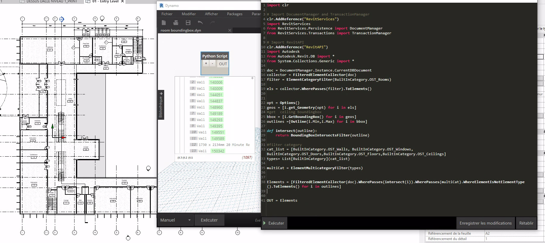
Response: One last question, is the bounding box actually a square box? I am wondering if it will capture rogue elements if the room is not square, for example a serpentine corridor.
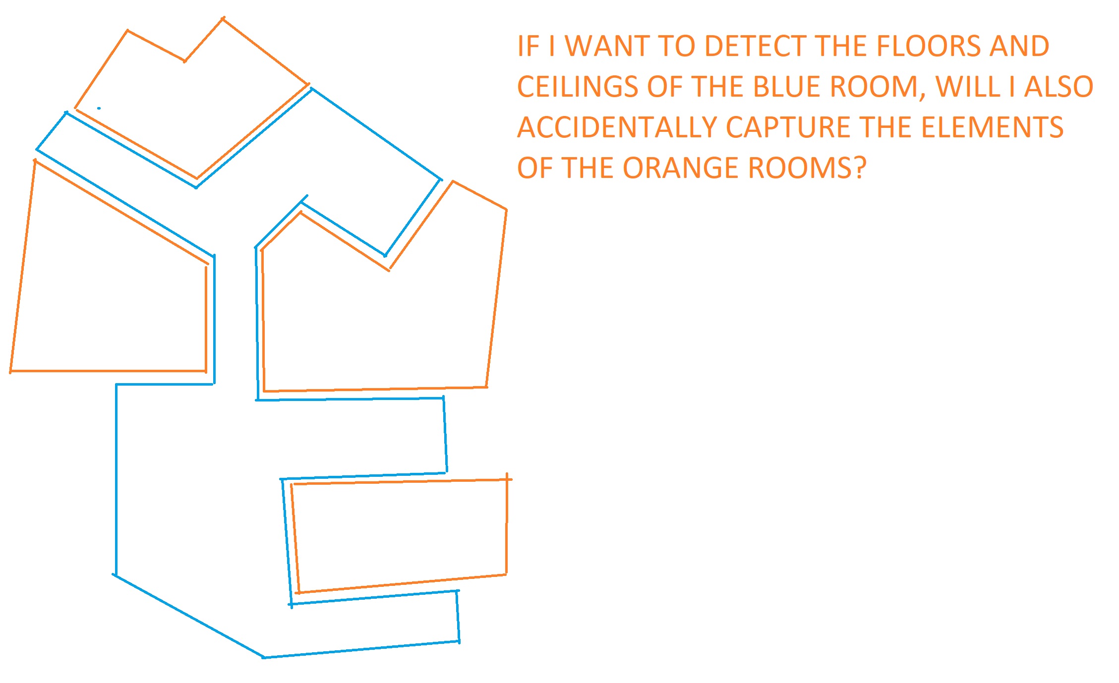
Answer: The BoundingBoxXYZ class
is a three-dimensional rectangular box at an arbitrary location and orientation within the Revit model.
However, the bounding box returned by the BIM element property is always a rectangular box, or, more precisely, a rectangular cuboid, with X, Y and Z axis-aligned faces.
Response: So, it would create a problem for a non-rectangular room right? (trying to detect related walls, floors and ceilings of a room).
Answer: I would try different approach for that.
You could try to use the IsPointInRoom method instead?
For ceiling, wall and floor, you can just take the centre points and project the points to the room.
Response: You say, 'project the points to room.' I'm not sure I understand this part. I guess you can draw a line from the centroid of the room to the centroid of the walls?
The inherent problem I see is that the centroid of each wall/floor/ceiling is going to be outside each room since it is its shell. It's almost like we need to offset each room's volume to encompass the centroids of its shells.
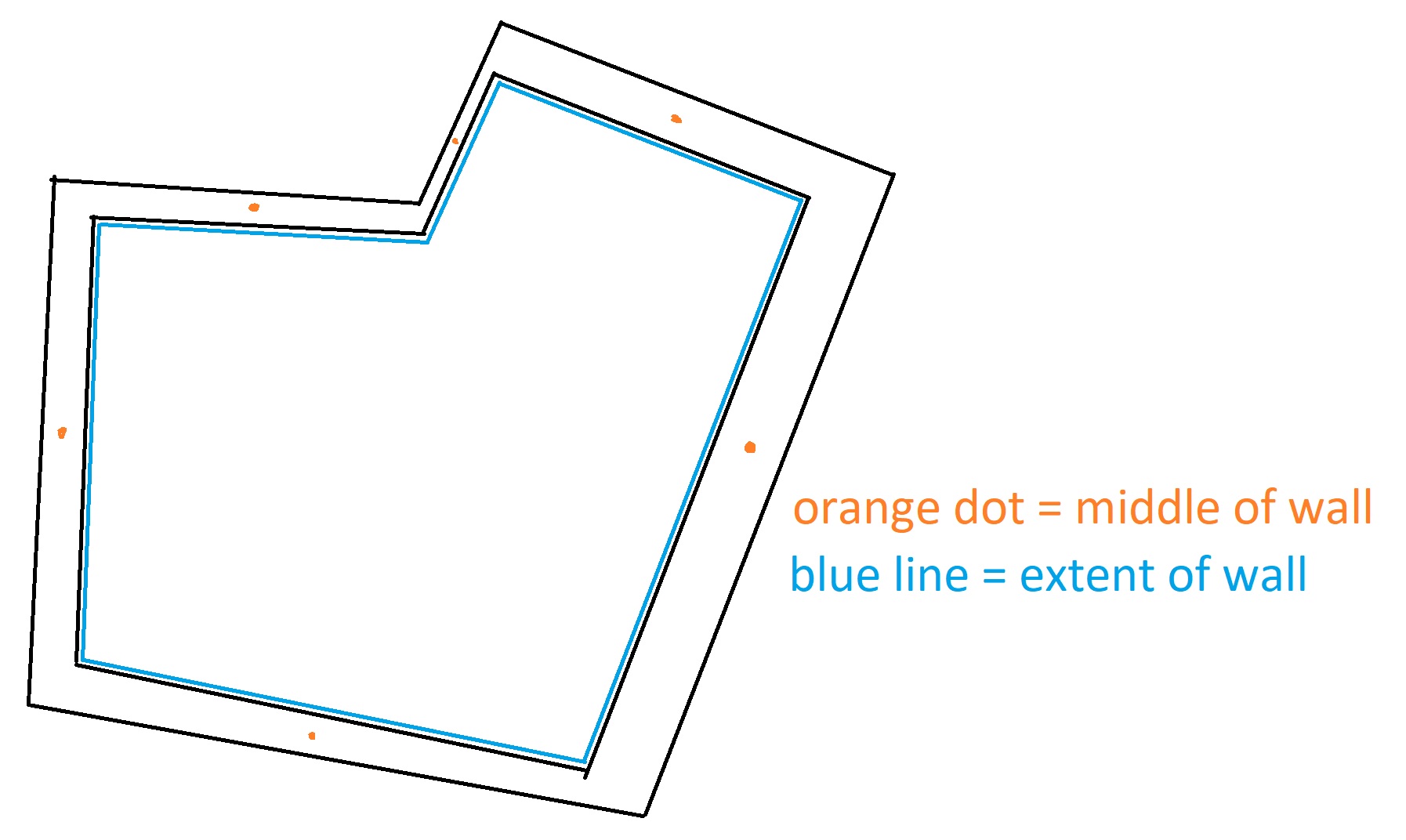
Typo:
- blue line = extent of room
Answer: Example: choose centre face of wall, then project the point according to normal by .
Then, use the IsPointInRoom method for each point; you should have 2 rooms for a single wall.
It is easier with ceilings and floor finishes.
Response: Interesting.
I can imagine lots of problems with this approach; for instance, a corridor that borders 20 rooms will only detect one room on each side.
Same with a floor or ceiling being shared by multiple rooms. Especially if the designers were lazy and modelled the floors/ceilings to go through walls.
It's a very interesting problem, I will keep pondering it. I'm actually surprised there's no direct way to do this directly in the API or in Revit schedules. Feels like every walls should know what rooms accost them and all rooms should know what surfaces bound them.
Answer: I think you can start another thread on that particular topic.
In the meantime, I think the first question has been resolved.
Many thanks to Samuel and Yien for the interesting discussion, and to Yien for all his good suggestions!
Comic Sans is a Public Good
Moving away for the Revit API for a moment, I am a bit of a typography junkie and pay far too much fanatic attention to that aspect of a text.
I sometimes even feel compelled to reformat a text more nicely to suit my taste just to make it more readable before I even start to take it in.
Until now, I have always gone for pretty traditional fonts and avoided Comic Sans.
I was interested and surprised to learn that there are good reasons not to do so, though, reading about the reason Comic Sans is a public good.