Dashboard, CreateViaOffset and Room Outer Outline
An inconclusive struggle to use CurveLoop.CreateViaOffset leads us once again to thank the powers that be for the integer-based 2D Boolean Clipper library, and some thoughts on project dashboards:
- Extracting data for project dashboard
- Specifying a list of offsets to
CreateViaOffset - Alternatives to determine room outline including surrounding walls
Extracting Data for Project Dashboard
Question: We are investigating whether some parts of our project management procedures can be automated. Today, we create an overview using PowerBI on project progression by combining data from financials, project controlling (hours, job packages etc.) and the likes. However, progress on the content and completion of design tasks is done manually with input from the project manager, making it difficult to track progress directly.
The assumption is that many of our graphic files such as .dwg contain data that describes how many documents that have been created and how many tasks have been completed. If can to extract this data, it could be built into some tool to provide an overview.
Let’s imagine we are preparing a renovation of a building and know that we have to complete a set number of PI diagrams as part of the overall design. If this information can easily be extracted from the .dwg files, we could add this to the PowerBI datasets to be included in the overall reporting.
Today, many projects are running smoothly due to experienced project leaders. We would like to create smooth systems to support the process as well as mitigate the risk of not being able to attract senior or skilled enough people to handle the project.
We tried to investigate whether or not information/lists/drawing overviews from Revit and AutoCAD can be exported into something like .csv, .xlsx and similar user/human friendly formats. Until now, we have not been able to answer this question. We have talked with different people from Autodesk chat support and read several of your blog post answers.
Could you somehow simplify this for me? Is it at all possible to generally export overview of the content of a dwg file in a simple format readable for other applications?
Answer: I am not currently very involved with AutoCAD and DWG development, more with Revit RVT.
However, I can certainly confirm that it is definitely both possible and easy to extract all the data you can possibly want from both of them.
You can do that using AutoCAD and Revit add-ins making use of the desktop .NET APIs.
If you are making use of any cloud-based workflows and storage, you can also do so online in the web, e.g., making use of the Forge APIs.
In fact, several people have already done so to create a number of different so-called dashboards that implement exactly what you are asking for.
Here are two in-depth demonstrations of such technology from Autodesk University 2018, a year ago:
- Using Forge to revolutionise coordinated project information
- How to Use Forge and BIM 360 to get insight and improve the BIM management of your project
By the way, the latter also mentions PowerBI.
These are just two random hits that popped up in my first quick Internet search for Autodesk Forge project overview.
Maybe you should try it yourself with 'dashboard' and other such terms.
There are probably much more advanced samples available today, a year later.
Here is a link to view all Forge samples.
You might also want to search for 'dashboard' on the Forge blog site using the Google search string dashboard site:forge.autodesk.com/blog.
Specifying a List of Offsets to CreateViaOffset
Stephen Harrison has been valiantly and persistently working on a solution to crop views to rooms, as discussed in the Revit API discussion forum threads on room boundary polygons, CreateViaOffset to offset room boundary inwards or outwards and CreateViaOffset taking a list of offset distances.
I set up the CropViewToRoom GitHub repository to play around with various approaches.
I now received some useful guidance from the development on the latest question in this series:
Question: I have raised a previous post regarding generating views from rooms but feel that has probably run its course.
The problem I now face is how to follow the outer face of the wall where the wall changes thickness over its length and when room separators are utilised.
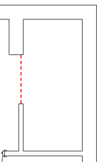
When the walls step back like this, there is an error “Curve loop couldn't be properly trimmed”:
Walls with varying thicknesses
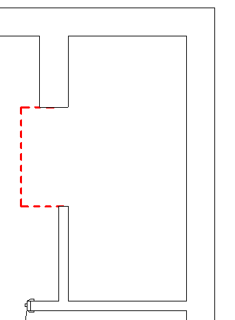
Regarding room separators, another problem occurs with a separator like this, Error “Curve loop couldn't be properly trimmed”:
Walls with room separator
There have been no errors so far in situations like this:
Walls with room separator offset
I am working in C# with Revit 2020 and utilising the following to create the offset:
  CreateViaOffset(
    CurveLoop original,
    IList<double> offsetDists,
    XYZ normal)
offsetDists is set to the thicknesses of the surrounding walls plus a standard set offset for the room separator.
Answer: I integrated and cleaned up your code in CropViewToRoom release 2020.0.0.2 for further analysis.
I have not solved it yet, but at least uncovered one definite problem.
In the room separator model, the curve loop that you assemble has 11 elements, whereas the wall thickness list only has 10. That obviously causes a problem.
I implemented a new method CreateModelCurves that creates a set of model curves to display the curve loop:
  void CreateModelCurves(
    View view,
    CurveLoop loop )
  {
    Document doc = view.Document;
    SketchPlane sp = view.SketchPlane;

    foreach( Curve curve in loop )
    {
      doc.Create.NewModelCurve( curve, sp );
    }
  }
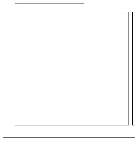
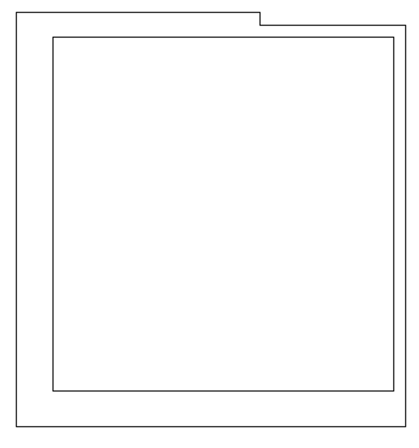
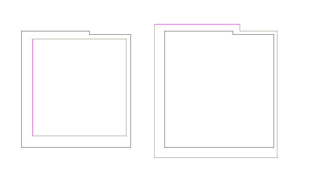
The result for the room separator model looks like this:
Room separator boundary model curve loop
I leave it up to you to figure out where that extra segment is coming from, what it represents, and how to deal with the wall thickness for that one.
Maybe that will help sort out the other issue as well.
I also reproduced the exception you mentioned creating the offset loop for the wall thickness sample model RVT.
I sent the following question to the development team for a usage example of the method to see what we might be doing wrong.
I am having trouble using the CreateViaOffset method taking a list of doubles for different offsets:
Can you provide a simple sample showing how to use this method?
I tested it passing in five curves representing the following five walls:
Rectangular room with five walls
Starting with the bottom horizontal wall and moving counterclockwise to the right, top two and left, I pass in five straight line segment curves and curves and the corresponding five offset distances:
  5 curves with lengths 9.19,9.51,3.61,5.58,9.51
  and 5 thicknesses 1.08,.43,.43,.76,1.08
This call throws an Autodesk.Revit.Exceptions.InvalidOperationException saying 'Curve loop couldn't be properly trimmed.'
Answer from the development team: In the customer's example, it looks like one of the walls is split in two and meet in the middle. Perhaps the curves he has are not colinear to start? That, it would seem, could easily result in a disconnected loop.
This is a sample from our add-in code:
  // previously filled list with simple double
  // values that represent the distance to offset;
  // that distance is calculated as the length of
  // a segment that is perpendicular on the curve
  // to be offset

  List<double> offsetArray;
  IList<Curve> polyCurves = new List<Curve>();

  foreach( var curve in contour3D.curves )
  {
    polyCurves.Add( curve.asRevitCurve(
      doc.Application ) );
  }

  if( polyCurves.none() )
    return false;

  CurveLoop curveLoop = CurveLoop.Create(
    polyCurves );

  if( curveLoop != null )
  {
    XYZ normal = XYZ.BasisZ;

    if( curveLoop.HasPlane() )
      normal = curveLoop.GetPlane().Normal;

    curveLoop = CurveLoop.CreateViaOffset(
      curveLoop, offsetArray, normal );

    if( curveLoop != null )
    {
      // do stuff with curve
    }
  }
It's nothing special. BUT...
I suspect the problem stems from the little vertical segment where the different width walls meet. We had problems with this method treating small segments from a structural contour, so the code above is put in a big try/catch and if it fails, we go to another offset algorithm that is far worse in general but treats small segments/self-intersections slightly better (Revit's offset seems more sceptical to prolong segments when it's the case, and I couldn't find code for self-intersections). L.E. Edited testing assumptions that are invalid since offset is positive, not negative.
I tested on our code the drawing provided as follows: the contour line is based on the exterior contour of the wall; the first curve in loop is the small one, contour being parsed clockwise; based on your/their code, the offset array is:
  [0]   0.75616799999999995 double
  [1]   0.42808400000000002 double
  [2]   0.42808400000000002 double
  [3]   1.0842520000000000  double
  [4]   1.0842520000000000  double
  [5]   0.75616799999999995 double
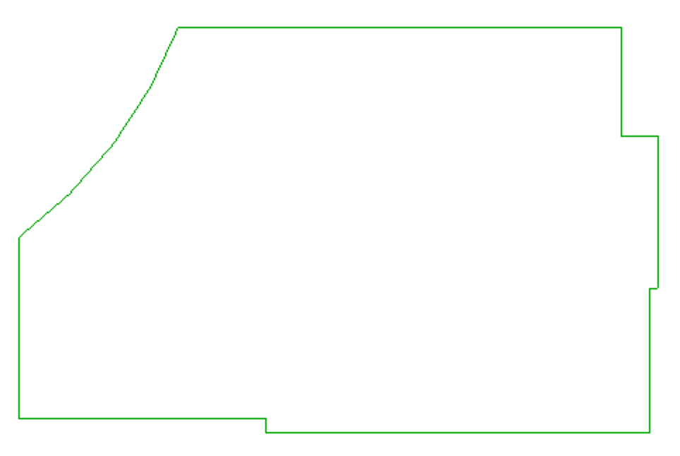
I tried both positive and negative offsets, and here is the result:
Successful result
No exceptions, everything worked.
I still stand on my original assumption that it has to do with the small segment, depending on the epsilon set by the add-in; instead of using wall thickness + 0.1 (which is in imperial feet, if not converted), you may try with a fixed percentage based on the wall thickness instead, e.g., 5-10%? – that may reduce problems with peculiar situations like teeny weeny tiny segments after offset that can't be handled properly.
Response: Thank you again for your time and patience in helping me resolve this issue. It is much appreciated.
All my tests would suggest that the suspected short vertical were the walls meet is the problem. However, I make the following observations.
I have previously tried a fixed percentage based on the wall thickness instead of +0.1 but received the same error.
I have tried exaggerated the wall thickness difference substantially and still received the same error.
If I have understood the response from the development team correctly, the solution they have proposed needs to be placed in a try catch as it may still fail and a therefore a more complex solution is required in this instance ? Is this alternative solution available through the API and if so, how may it be implemented?
Answer: Yes, they suggest using a moderate percentage of the wall thickness, I believe, e.g., 10-20%. I guess that for your needs, 110-120% is required. They also say that they tested it that way, and it worked well, offsetting both inwards and outwards. The sample code that they provided was extracted from some internal Revit module and is thus not present in the SDK nor restricted to using the public API. It just shows an example of using the method, regardless of where the input comes from.
I'll try out this percentage thingy on your sample models and see how I fare.
Later: I tried to follow the devteam suggestion of using a percentage instead of a fixed additional offset, and it did not work for me at all.
I tried both 110%, which would suit your needs, and 10%.
In both cases, it still throws the InvalidOperationException saying 'loop couldn't be properly trimmed.'
Maybe they tested on a more recent development version of Revit.
So, I think it might be time to step away from CreateViaOffset for the time being.
On the other hand, your goal is almost reached: you have the room boundary, its boundary elements and their thicknesses. From those, it is possible to create a curve loop tracing the outside edges of the walls.
How to Determine Room Outline Including Surrounding Walls
Question: I started to look at the possibility of tracing the outside of the walls several weeks ago, when I was at a loss utilising CreateViaOffset.
I was finding it difficult to create the closed loop necessary, and particularly how I would achieve this were the wall thickness changes across its length.
Could you point me in the right direction, possibly some sample code that I could examine and see if I could get it to work to my requirements.
Hope you have a good festive season.
Answer: I see several possible alternative approaches avoiding the use of CreateViaOffset, based on:
- Room boundary curves and wall thicknesses
- Room boundary curves and wall bottom face edges
- Projection of 3D union of room and wall solids
- 2D union of room and wall footprints
The most immediate and pure Revit API approach would be to get the curves representing the room boundaries, determine the wall thicknesses, offset the wall boundary curves outwards by wall thickness plus minimum offset, and ensure that everything is well connected by adding small connecting segments in the gaps where the offset jumps.
Several slightly more complex pure Revit API approaches could be designed by using the wall solids instead of just offsetting the room boundary curves based on the wall thickness. For instance, we could query the wall bottom face for its edges, determine and patch together all the bits of edge segments required to go around the outside of the wall instead of the inside.
Slightly more complex still, and still pure Revit API: determine the room closed shell solid, unite it with all the wall solids, and make use of the extrusion analyser to project this union vertically onto the XY plane and grab its outside edge.
Finally, making use of a minimalistic yet powerful 2D Boolean operation library, perform the projection onto the XY plane first, and unite the room footprint with all its surrounding wall footprints in 2D instead. Note that the 2D Booleans are integer based. To make use of those, I convert the geometry from imperial feet units using real numbers to integer-based millimetres.
The two latter approaches are both implemented in my ElementOutline add-in.
I mentioned it here in two previous threads:
Probably all the pure Revit API approaches will run into various problematic exceptional cases, whereas the 2D Booleans seem very fast, reliable and robust and may well be able to handle all the exceptional cases that can possibly occur, so I would recommend trying that out first.
I hope this suggestion makes for a nice gift to you in this festive season.
Happy advent!