Room Closed Shell DirectShape for Forge Viewer
I explored three main topics here at the Forge accelerator:
- Room closed shell solid visibility in the Forge viewer
- Rebar simplification: replace rebar elements with simplified solids or model curves
- glTF export
Today, I'll dive deeper into the first:
- IFC exporter utility adds new built-in parameter
- Barcelona Forge accelerator
- Room closed shell in the Forge viewer
- Triangulate the solid face by face
- Triangulate entire solid
- Tessellation accuracy control documentation error
IFC Exporter Utility Adds New Built-In Parameter
Before that, however, here is an interesting topic from the Revit API discussion forum.
Quite surprisingly, for me, the IFC exporter utilities enable you to add your own new IFC related built-in parameter to an element.
I was previously not aware of any way to add new built-in parameters to existing elements lacking them.
This solution was discovered and shared by Luis González Torquemada in his thread on adding an IFC_GUID BuiltInParameter to a beam that doesn't contain such a parameter:
Question: I've created a beam by
  FamilyInstance instance
    = document.Create.NewFamilyInstance( beamLine,
      famSymbol, level, StructuralType.Beam );
Now I need to set a particular IFC_GUID value to this element (it comes from another application), but
  Parameter ifcParam = instance.get_Parameter(
    BuiltInParameter.IFC_GUID );
returns null.
How can I add this parameter (some other elements in the same document have this parameter)?
The issue I want to solve with this question is:
When Revit imports a beam from an IFC file, the StructuralType of the Element (or FamilyInstance) is StructuralType.NonStructural instead of StructuralType.Beam.
So, you can’t assign it any family symbol of BuiltInCategory.OST_StructuralFraming (not via API, nor via the Revit menu).
So, I must delete the element and create a new one with the correct StructuralType.Beam and the same IFC_GUID.
Note that this issue doesn’t arise with structural columns.
Answer: I do not believe you can add a built-in parameter to an element that does not have it already.
Response: I’ve found it! The solution is:
  ElementId eid = new ElementId(
    BuiltInParameter.IFC_GUID );

  Autodesk.Revit.DB.IFC.ExporterIFCUtils.AddValueString(
    instance, eid, ifcguid );
If you create a new beam with the API, the Parameters property of the beam doesn't contain a IFC_GUID member, and get_Parameter(BuiltInParameter.IFC_GUID) returns null.
After using the code above, get_Parameter(BuiltInParameter.IFC_GUID) returns correctly and Revit shows it in the properties pane.
By the way, can you tell me how can I change the StructuralType property of an Element from NonStructural to Beam?
Answer: I did not know (or believe!) that you can add a new built-in parameter to an element.
So that functionality is rather special.
Unfortunately, the StructuralType property is read-only, so you cannot change it:
I guess the only way to define it is during creation.
So, you are doing the right thing creating new beams.
Barcelona Forge Accelerator
Traditionally, Thursday evening is the time for the Forge accelerator celebratory dinner:

Among our participants we welcome Álvaro Pérez, Manrique Gómez and Luis López of the AECOM BIM team in Madrid, who say:
We have been developing desktop solutions for Revit for years and are currently moving to the cloud and the Forge platform.
The experiences at this Forge accelerator in Barcelona are invaluable for us thanks to all the support from the Autodesk guys.

Posing for us in the background, you can also admire the table-tennis skills of Forge experts Adam and Petr.
Room Closed Shell in the Forge Viewer
I recently implemented an external command
that creates DirectShape elements to represent room volumes.
The code is available in
the RoomVolumeDirectShape GitHub repository.
The initial implementation was very simple, since the Room.GetClosedShell method returns a GeometryElement that can be passed straight into the direct shape SetShape method with no further ado.
Unfortunately, on further testing, we discovered that the resulting generic model direct shape elements do not show up as expected in the viewer.
No geometry is displayed for it, and it is not even listed in the model browser.
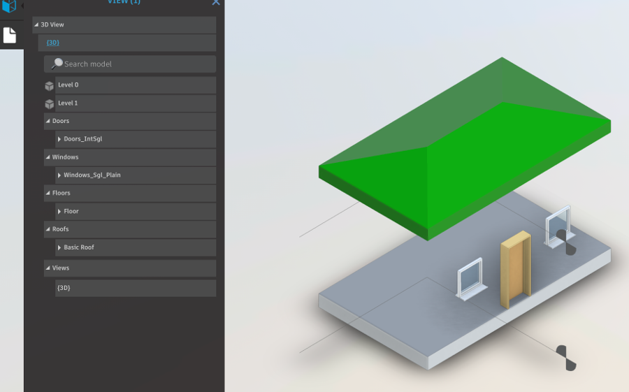
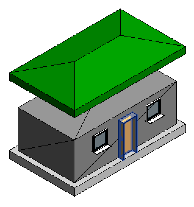
Here is a Forge view of a room. It contains a direct shape representing the room volume. It appears perfectly fine in Revit. However, in the Forge viewer, no trace of it is visible:
This led to a lot of head scratching and further research.
Apparently, the solid returned by the Revit API for the room closed shell is flawed in some way.
I explored a number of approaches to fix it, then took recourse to recreating the entire solid from scratch in various ways, two of which turned out to produce reliable results so far:
- Fix it somehow
- Triangulate face by face
- Recreate solid using
EdgeLoops– orientation needs to be fixed - Recreate solid using
GetEdgesAsCurveLoops– orientation needs to be fixed - Triangulate entire solid using the
SolidUtilsTessellateSolidOrShellmethod
Most of my efforts are preserved in the source code, enclosed in #if pragmas.
Triangulate the Solid Face by Face
One reliable way to generate a valid solid to replace the flawed one produced by GetClosedShell is to query each face of the solid for its triangulation and use the triangular facets to define the direct shape instead, as described in the discussion
on creating a DirectShape element from a face mesh.
The following code achieves this:
/// <summary>
/// Create a new list of geometry objects from the
/// given input. As input, we supply the result of
/// Room.GetClosedShell. The output is the exact
/// same solid lacking whatever flaws are present
/// in the input solid.
/// </summary>
static IList<GeometryObject> CopyGeometry(
  GeometryElement geo,
  ElementId materialId )
{
  TessellatedShapeBuilderResult result = null;

  TessellatedShapeBuilder builder
    = new TessellatedShapeBuilder();

  int nFaces = 0;
  int nTriangles = 0;
  List<XYZ> vertices = new List<XYZ>( 3 );

  foreach( GeometryObject obj in geo )
  {
    Solid solid = obj as Solid;

    if( null != solid )
    {
      if( 0 < solid.Volume )
      {
        builder.OpenConnectedFaceSet( false );

        // Iterate over the individual solid faces

        foreach( Face f in solid.Faces )
        {
          vertices.Clear();

          Mesh mesh = f.Triangulate();
          int n = mesh.NumTriangles;

          for( int i = 0; i < n; ++i )
          {
            MeshTriangle triangle = mesh.get_Triangle( i );

            XYZ p1 = triangle.get_Vertex( 0 );
            XYZ p2 = triangle.get_Vertex( 1 );
            XYZ p3 = triangle.get_Vertex( 2 );

            vertices.Clear();
            vertices.Add( p1 );
            vertices.Add( p2 );
            vertices.Add( p3 );

            TessellatedFace tf
              = new TessellatedFace(
                vertices, materialId );

            if( builder.DoesFaceHaveEnoughLoopsAndVertices( tf ) )
            {
              builder.AddFace( tf );
              ++nTriangles;
            }
          }

          builder.AddFace( new TessellatedFace(
            vertices, materialId ) );

          ++nFaces;
        }
        builder.CloseConnectedFaceSet();
        builder.Target = TessellatedShapeBuilderTarget.AnyGeometry;
        builder.Fallback = TessellatedShapeBuilderFallback.Mesh;
        builder.Build();
        result = builder.GetBuildResult();
      }
    }
  }
  return result.GetGeometricalObjects();
}
Unfortunately, all the triangle edges remain visible in the Revit model, even interior edges lying inside a planar face:
Triangulate Entire Solid
One serious problem may arise triangulating each face separately as shown above:
If two face meeting in a curved edge are independently triangulated, their respective tessellation of the shared edge may differ, resulting in triangle vertices on one face not matching the ones on the other, causing gaps in the resulting solid.
That can be solved only by triangulating the entire solid in one fell swoop, which can be easily achieved using the SolidUtils TessellateSolidOrShell method as follows.
This code also includes some traces of initial experiments exporting glTF facet data:
  TessellatedShapeBuilderResult result = null;

  TessellatedShapeBuilder builder
    = new TessellatedShapeBuilder();

  int nTriangles = 0;
  List<XYZ> vertices = new List<XYZ>( 3 );

  // Collect data for glTF: a list of vertex
  // coordinates in millimetres, and a list of
  // triangle vertex indices into the list.

  List<int> gltfVertexCoordinates = new List<int>();
  List<int> gltfVertexIndices = new List<int>();
  int gltfVertexIndexBase = 0;

  foreach( GeometryObject obj in geo )
  {
    Solid solid = obj as Solid;

    if( null != solid )
    {
      if( 0 < solid.Volume )
      {
        builder.OpenConnectedFaceSet( false );

        Debug.Assert(
          SolidUtils.IsValidForTessellation( solid ),
          "expected a valid solid for room closed shell" );

        SolidOrShellTessellationControls controls
          = new SolidOrShellTessellationControls()
          {
            //
            // Summary:
            //     A positive real number specifying how accurately a triangulation should approximate
            //     a solid or shell.
            //
            // Exceptions:
            //   T:Autodesk.Revit.Exceptions.ArgumentOutOfRangeException:
            //     When setting this property: The given value for accuracy must be greater than
            //     0 and no more than 30000 feet.
            // This statement is not true. I set Accuracy = 0.003 and an exception was thrown.
            // Setting it to 0.006 was acceptable. 0.03 is a bit over 9 mm.
            //
            // Remarks:
            //     The maximum distance from a point on the triangulation to the nearest point on
            //     the solid or shell should be no greater than the specified accuracy. This constraint
            //     may be approximately enforced.
            Accuracy = 0.03,
            //
            // Summary:
            //     An number between 0 and 1 (inclusive) specifying the level of detail for the
            //     triangulation of a solid or shell.
            //
            // Exceptions:
            //   T:Autodesk.Revit.Exceptions.ArgumentOutOfRangeException:
            //     When setting this property: The given value for levelOfDetail must lie between
            //     0 and 1 (inclusive).
            //
            // Remarks:
            //     Smaller values yield coarser triangulations (fewer triangles), while larger values
            //     yield finer triangulations (more triangles).
            LevelOfDetail = 0.1,
            //
            // Summary:
            //     A non-negative real number specifying the minimum allowed angle for any triangle
            //     in the triangulation, in radians.
            //
            // Exceptions:
            //   T:Autodesk.Revit.Exceptions.ArgumentOutOfRangeException:
            //     When setting this property: The given value for minAngleInTriangle must be at
            //     least 0 and less than 60 degrees, expressed in radians. The value 0 means to
            //     ignore the minimum angle constraint.
            //
            // Remarks:
            //     A small value can be useful when triangulating long, thin objects, in order to
            //     keep the number of triangles small, but it can result in long, thin triangles,
            //     which are not acceptable for all applications. If the value is too large, this
            //     constraint may not be satisfiable, causing the triangulation to fail. This constraint
            //     may be approximately enforced. A value of 0 means to ignore the minimum angle
            //     constraint.
            MinAngleInTriangle = 3 * Math.PI / 180.0,
            //
            // Summary:
            //     A positive real number specifying the minimum allowed value for the external
            //     angle between two adjacent triangles, in radians.
            //
            // Exceptions:
            //   T:Autodesk.Revit.Exceptions.ArgumentOutOfRangeException:
            //     When setting this property: The given value for minExternalAngleBetweenTriangles
            //     must be greater than 0 and no more than 30000 feet.
            //
            // Remarks:
            //     A small value yields more smoothly curved triangulated surfaces, usually at the
            //     expense of an increase in the number of triangles. Note that this setting has
            //     no effect for planar surfaces. This constraint may be approximately enforced.
            MinExternalAngleBetweenTriangles = 0.2 * Math.PI
          };

        TriangulatedSolidOrShell shell
          = SolidUtils.TessellateSolidOrShell( solid, controls );

        int n = shell.ShellComponentCount;

        Debug.Assert( 1 == n,
          "expected just one shell component in room closed shell" );

        TriangulatedShellComponent component
          = shell.GetShellComponent( 0 );

        gltfVertexIndexBase = gltfVertexCoordinates.Count;

        n = component.VertexCount;

        for(int i = 0; i < n;  ++i )
        {
          XYZ v = component.GetVertex( i );
          gltfVertexCoordinates.Add( FootToMm( v.X ) );
          gltfVertexCoordinates.Add( FootToMm( v.Y ) );
          gltfVertexCoordinates.Add( FootToMm( v.Z ) );
        }

        n = component.TriangleCount;

        for( int i = 0; i < n;  ++i )
        {
          TriangleInShellComponent t
            = component.GetTriangle( i );

          vertices.Clear();

          vertices.Add( component.GetVertex( t.VertexIndex0 ) );
          vertices.Add( component.GetVertex( t.VertexIndex1 ) );
          vertices.Add( component.GetVertex( t.VertexIndex2 ) );

          gltfVertexIndices.Add( gltfVertexIndexBase + t.VertexIndex0 );
          gltfVertexIndices.Add( gltfVertexIndexBase + t.VertexIndex1 );
          gltfVertexIndices.Add( gltfVertexIndexBase + t.VertexIndex2 );

          TessellatedFace tf = new TessellatedFace(
            vertices, materialId );

          if( builder.DoesFaceHaveEnoughLoopsAndVertices( tf ) )
          {
            builder.AddFace( tf );
            ++nTriangles;
          }
        }

        builder.CloseConnectedFaceSet();
        builder.Target = TessellatedShapeBuilderTarget.AnyGeometry;
        builder.Fallback = TessellatedShapeBuilderFallback.Mesh;
        builder.Build();
        result = builder.GetBuildResult();

        // Log glTF data

        Debug.Print(
          "{0} glTF vertex coordinates in millimetres:",
          gltfVertexCoordinates.Count );
        Debug.Print( string.Join( " ",
          gltfVertexCoordinates.Select<int, string>(
            i => i.ToString() ) ) );
        Debug.Print(
          "{0} glTF triangle vertex indices:",
          gltfVertexIndices.Count );
        Debug.Print( string.Join( " ",
          gltfVertexIndices.Select<int, string>(
            i => i.ToString() ) ) );

        // Save glTF data to binary file

        using( FileStream file = File.Create( "C:/tmp/" + _gltf_path ) )
        {
          using( BinaryWriter writer = new BinaryWriter( file ) )
          {
            foreach( int i in gltfVertexCoordinates )
            {
              writer.Write( (float) i );
            }
            foreach( int i in gltfVertexIndices )
            {
              Debug.Assert( ushort.MaxValue > i,
                "expected triangle vertex indices to fit into unsigned short" );
              writer.Write( (ushort) i );
            }
          }
        }
      }
    }
  }
  return result.GetGeometricalObjects();
Note that this approach enables the use of the SolidOrShellTessellationControls, which provide a great degree of control over the tessellation accuracy, something that developers have long been clamouring for.
And, also importantly, as noted above, the result of this call is guaranteed to be a valid watertight closed shell, unlike most other approaches provided by the Revit API.
Solid or Shell Tessellation Accuracy Control Documentation Error
Among the many issues I faced, this was one of the most trivial ones:
The Revit API documentation of the SolidOrShellTessellationControls.Accuracy property states:
- The given value for accuracy must be greater than 0 and no more than 30000 feet.
In my initial test, I specified an accuracy of 0.003, corresponding to ca. 0.9 mm, which clearly fulfils that requirement.
An exception was thrown.
I raised it to 0.006, a bit over 1.8 mm, and it passed.
In the end, as you can see above, I raised it further, to 0.03, a bit over 9 mm.
I assume the true minimum limitation correlates with the Revit minimum model line length limit, which is around 1/16th of an inch.
  jc> inch = 25.4

  jc> foot = 12 * inch = 304.8

  jc> minlen = inch / 16 = 1.5875

  jc> accuracy = 0.003

  jc> accuracy * foot = 0.9144

  jc> 0.006 * foot = 1.8288
Coming up:
- Rebar simplification: replace rebar elements with simplified solids or model curves
- glTF export of room volumes