Scaling, Face and Mesh Triangle Normals
Let's look at a couple of scaling and triangle orientation issues that recently came up:
- Transform and scaling in Forge
- ModPlus and scaling text in dockable panel
- Exporting view image extents
- Mesh triangle orientation
PlanarFacenormal
Transform and Scaling in Forge
Konrad Sobon of @arch_laboratory raised a question on scaling and transformation of a Revit model in the Forge viewer:
Question: Quick question. I noticed that you recently talked about exporting room boundaries to CSV to be imported into Forge.
I am curious about the process of actually importing extra geometrical data into Forge, and if you have any samples you can share.
I am specifically trying to get things like location points for certain families to be able to dimension to them using the measuring tool in Forge. The thing is that reference points are technically not a mesh so they don't get exported to Forge during regular model derivative translation process. I was hoping to be able to export them to a CSV file, and import into Forge Viewer, creating custom three.js geometry just for that purpose. I am a little lost when it comes to any coordinates translations that I would have to apply. All my points when exported to default decimal feet coordinates end up all over the place. Any ideas?
Answer: In my experiments connecting desktop and cloud, the Forge viewer just replicated the internal Revit database units one to one.
Response: Sure. I have been looking at this some more, and there seems to be an offset applied that is based on the bounding box size. Perhaps Forge Viewer measures centre of the geometry bounding box, and places that at 0,0,0? That would explain the offset. Thoughts?
Answer: Yes, that is an extremely viable theory. I think I have indeed heard that exact explanation in the past. Origin at the centre, unity scaling, i.e., imperial feet, the internal Revit database units.
ModPlus and Scaling Text in Dockable Panel
Alexander Pekshev, aka Александр Пекшев is
the author of the ModPlus blog,
where he published an interesting article explaining how
to correct the problem of incorrect display of the contents of the Dockable Panel when the screen is scaled using
a .NET Decorator class.
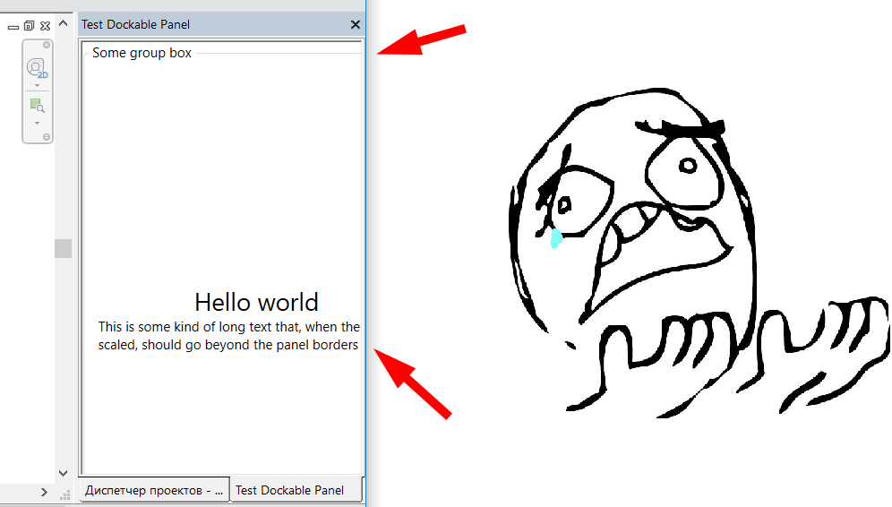
This problem is apparently fixed in Revit 2019, so the solution is relevant for the preceding versions.
The Decorator class still has other uses as well, of course.
Exporting View Image Extents
Starting to move away from the topic of scaling, but still vaguely related, some interesting conversations took place in the Revit API discussion forum on how to get the extents when exporting an image from a view, again vaguely related to exporting images of all my doors.
If you have any questions about image export, check them out.
Mesh Triangle Orientation
Two other discussions on the recurring topic of triangle orientation.
First, about the normal of a mesh triangle:
Question: I am using a series of triangle meshes to form a polyhedron as an approximation of a very complicated solid.
Therefore, I triangulate each face of the solid with face.Triangulate and collect those triangle meshes. However, I found that the triangle meshes don't have normals. I am wondering how to get the correct normal for each triangle, that points outwards from the polyhedron.
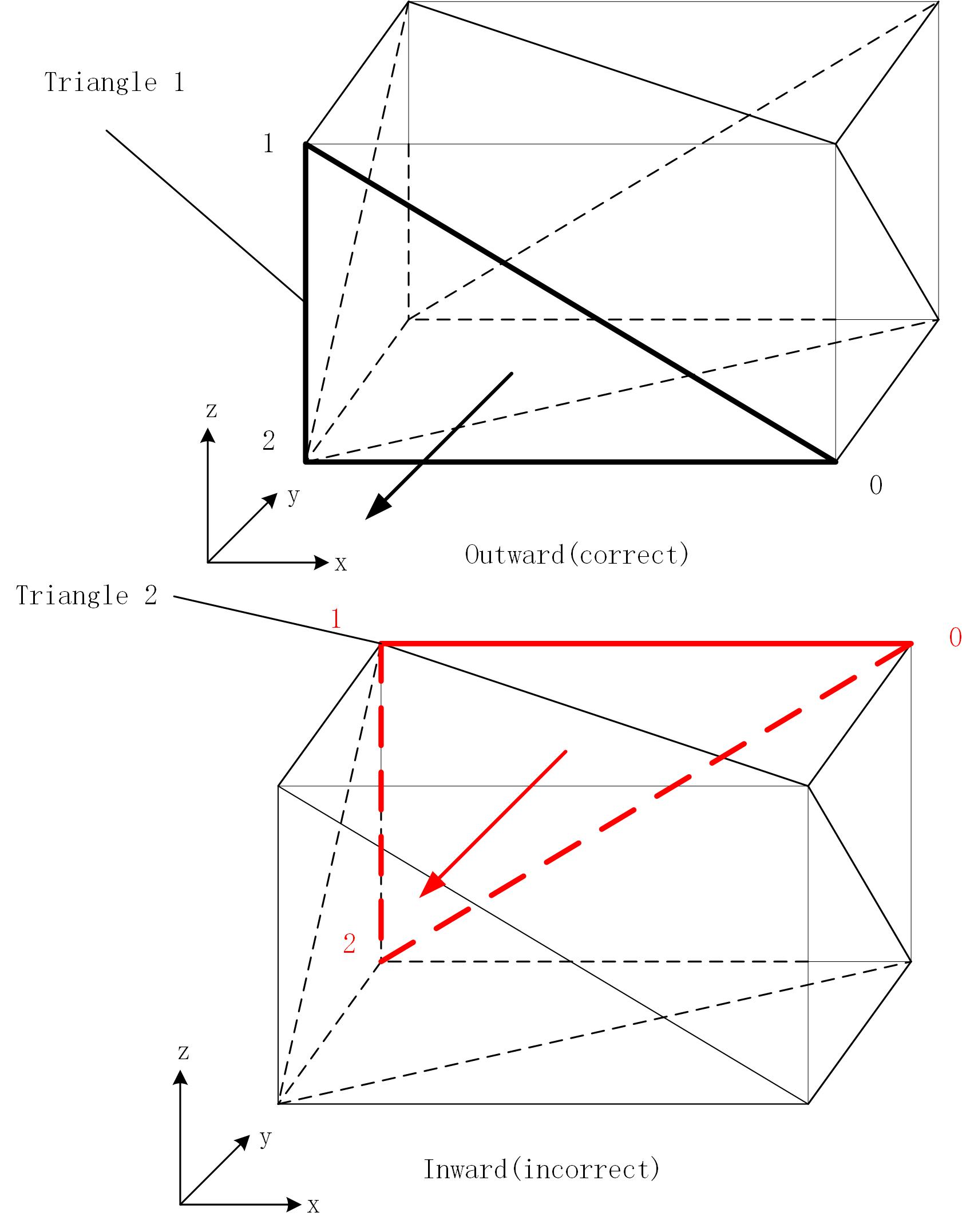
Answer: Number each triangle's vertices clockwise from 1 to 3, then take something like (x3-x1).CrossProduct(x2-x1). Of course, this local numbering should be consistently enforced globally in the provided mesh data to fix the sign, otherwise you will have some pointing inward, some outward of your polyhedron.
Response: I am wondering how to determine the 'right' clockwise or counter-clockwise orientation of a triangle. As is shown in the figure below, the vertices of triangle 1 are arranged counterclockwise and the normal can be calculated correctly (right-hand rule is applied); however, those of triangle 2 are also arranged counterclockwise, but the normal is incorrect.
If every face of a solid is a planar face, that is not a problem because the triangles can directly get the face normal, but in my case, some faces are curved. Therefore, it is not easy to get the right normal directions.
Answer: You can calculate the normal on any face with the face.ComputeNormal method:
  Face f;
  XYZ MeshPt; // x1, x2 or x3
  XYZ NormalFromPoints; // (x3-x1).CrossProduct(x2-x1)
  UV UVpt = f.Project( MeshPt ).UVPoint;
  XYZ face_normal = f.ComputeNormal( UVpt );

  XYZ surface_normal
    = f.OrientationMatchesSurfaceOrientation
      ? face_normal
      : face_normal.Negate();

  XYZ MeshNormal = surface_normal
    .DotProduct( NormalFromPoints ) > 0
      ? NormalFromPoints
      : NormalFromPoints.Negate();
Response: I'm afraid I cannot use the method OrientationMatchesSurfaceOrientation, because I am working in the Revit 2017 API.
It was introduced as a surface and face API enhancement in Revit 2018.
I tested the code without that method and found that the normal calculated like this always returns the same direction as Face.Project:
  var tri = mesh.get_Triangle( I );
  XYZ pt0 = tri.get_Vertex( 0 );
  XYZ pt1 = tri.get_Vertex( 1 );
  XYZ pt2 = tri.get_Vertex( 2 );
  XYZ vec1 = pt1 - pt0;
  XYZ vec2 = pt2 - pt0;
  XYZ normal = vec1.CrossProduct( vec2 );
PlanarFace Normal
A closely related discussion asks about the opposition direction of Planarface.Normal:
Question: How can I convert PlanarFace.Normal to opposite direction?
Answer: Do you just want to get the opposite direction?
If so, just write -1 * PlanarFace.Normal or PlanarFace.Normal.Negate().
However, if you want to flip the face, it is not possible.
Here are some related discussions:
- Faces of the room from solid clockwise and counter-clockwise
- About the normal of a mesh triangle
- Incorrect face normal
I believe that, together, they answer all possible questions on face normals and mesh triangle orientation.
Note the tricky bits in the third discussion, explaining why you need to differentiate between:
- A picked face and the face returned by the element geometry.
- A face belonging to the symbol geometry (family definition coordinate space) and instance geometry (project coordinates).
Many thanks to @Revitalizer and @FAIR59 for their analysis and illuminating explanations in those threads!