Resources, Rotated Rebar Stirrups and Steel Stuff
I'll start this week with several solutions from the Revit API discussion forum and elsewhere, especially two different approaches to create rotated rebar stirrups:
- Embedded tooltip icon resource
- Revit 2019 tooltip videos are MP4
- How to read and write bolt, plate and weld
- Creating rotated rebar stirrups

Embedded Tooltip Icon Resource
Let's start with a quick question on the relative path for folder in order to load an icon image for an external command ribbon button:
Question: I am starting with a first Revit add in and one thing I am concerned is how to create the relative path for my icon URL as in the following code:
  // Determine the data for a push button,
  // include the name of the command to execute
  PushButtonData pushButtonData51
    = new PushButtonData( "DetachModels",
      "DetachModels", thisAssemblyPath,
      "CherryBIMservices.BatchDetachedModel" );

  //Add push button to the ribbon panel
  PushButton pushButton51 = ManagePanel.AddItem(
    pushButtonData51 ) as PushButton;

  // Add a tool tip for a button
  pushButton51.ToolTip = "Batch detach models";

  // Add URL of image, set as Bitmap and set
  // the image as the icon for the pushbutton
  Uri uriImage51 = new Uri( @"C:\ProgramData\Autodesk\Revit\Addins\2017\CherryBIMservices\51.png" );
  BitmapImage bitmapImage51 = new BitmapImage(
    uriImage51 );
  pushButton51.LargeImage = bitmapImage51;
My question is how to replace the absolute path to the icon file:
- C:\ProgramData\Autodesk\Revit\Addins\2017\CherryBIMservices\51.png
I would like to use a relative path instead.
Thank you so much for your help.
Answer: I would recommend embedding your icon as an embedded resource.
Here are two out of many related discussions of the topic by The Building Coder:
Then you will have no need for any file path at all, and life will be easy and sweet.
Revit 2019 Tooltip Videos are MP4
Next, a quick explanation why Revit 2019 tooltip ExpandedVideo does not work:
Question: I am migrating my existing plugin from Revit 2018 to Revit 2019. I see that the animation (.swf file) in the tool tip does not play. This works perfect with 2018 but not with 2019. The message says:

The flash version is 29.0.0171 (Latest Version). Are there any API changes in this section? Is it an issue with the Flash version?
Answer: All Revit 2019 tooltip videos are in MP4 format now.
You can see for yourself under:
- C:/Program Files/Autodesk/Revit 2019/videos
How to Read and Write Bolt, Plate and Weld
Here is a simple question that was not raised in the discussion forum and therefore is especially important to share here, at least:
Question: Revit added native Bolt, Plate & Weld in version 2019, but I can find related API to read/write them. Please advise where I can find them, and provide a sample on how to use them if possible.
Answer: You can find samples about how to create and read steel elements such as plates, bolts, welds, etc., in the Revit SDK sample:
- RevitSDK\Software Development Kit\Samples\SampleCommandsSteelElements
I hope this helps.
Response: Yes. It does. Thank you.
Creating Rotated Rebar Stirrups
Now for the main topic for today:
Question: I have an issue creating stirrups in rotated beams.
I originally described it in the thread on rotation of stirrup rebar in a rotated beam in the Revit structure forum, but it is in fact an API issue.
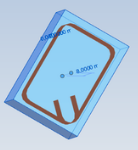
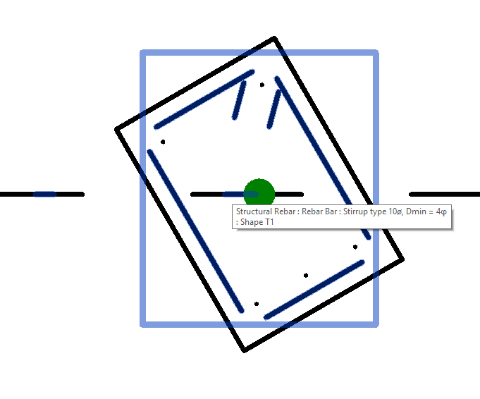
Here is an image showing the corrupted layout on a 30 degrees rotated beam – part of the rebar near the centre and outside:

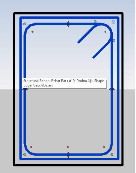
The correct layout looks like this:

Answer: I opened the RVT that was attached in the tread.
It generated many debug warnings about non-conformal matrix used in the Rebar element.
Probably, this happens because the rebar was created incorrectly, e.g., passing wrong arguments for origin, xVec and yVec.
I attached a TestCommand.cs file which achieves the job in two ways:
First solution is using the same functions that the customer used: Rebar.CreateFromRebarShape and rebar.ScaleToBox.
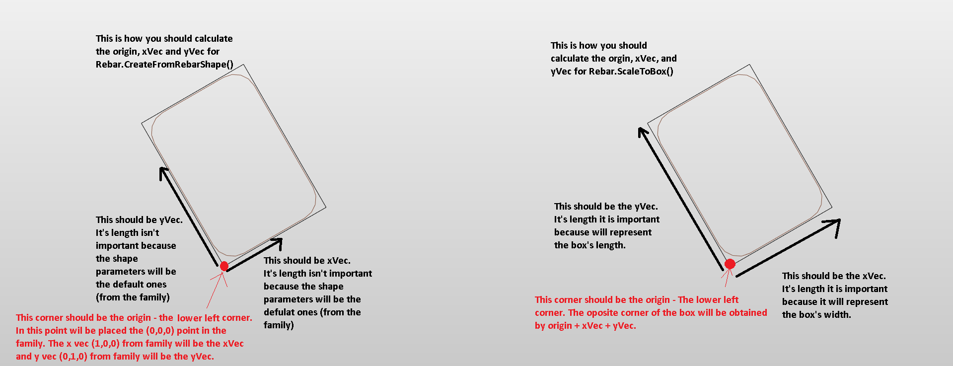
Here is an image to help understand what arguments you should pass:

It is very important how you pass origin, xVec and yVec, because this data is used to create the bar position transform.
It is a transformation from family coordinates (origin (0,0,0), xVec (1,0,0), yVec (0,1,0)) to the new position in the model (origin, xVec and yVec).
For the second solution, I used the Rebar.CreateFromCurves function.
Here is the complete code:
using System;
using System.Collections.Generic;

using Autodesk.Revit.DB;

using Autodesk.Revit.UI;
using Autodesk.Revit.UI.Selection;

using Autodesk.Revit.Attributes;
using Autodesk.Revit.DB.Structure;
using System.Windows.Forms;

namespace TestRebar
{
  [TransactionAttribute( TransactionMode.Manual )]
  public class TestRebar : IExternalCommand
  {
    UIApplication m_uiApp;
    Document m_doc;

    ElementId elementId = ElementId.InvalidElementId;

    public Result Execute(
      ExternalCommandData commandData,
      ref string message,
      ElementSet elements )
    {
      try
      {
        initStuff( commandData );
        if( m_doc == null )
          return Result.Failed;

        Element host = getRebarHost( commandData );
        if( host == null )
        {
          MessageBox.Show( "Null host" );
          return Result.Succeeded;
        }

        RebarShape shape = getRebarShape();
        if( shape == null )
        {
          MessageBox.Show( "Null shape" );
          return Result.Succeeded;
        }

        RebarBarType rebarType = getRebarBarType();
        if( rebarType == null )
        {
          MessageBox.Show( "Null rebarType" );
          return Result.Succeeded;
        }

        GeometryElement geometryElement
          = host.get_Geometry( new Options() );

        // this will get the edges in family coordinates
        // not the global coordinates

        IList<Curve> edges = getFaceEdges( geometryElement );

        Transform trf = Transform.Identity;
        FamilyInstance famInst = host as FamilyInstance;
        if( famInst != null )
          trf = famInst.GetTransform();

        // SOLUTION 1

        {
          XYZ origin, xAxisDir, yAxisDir, xAxisBox, yAxisBox;
          getOriginXandYvecFromFaceEdges( edges,
            out origin, out xAxisDir, out yAxisDir,
            out xAxisBox, out yAxisBox );

          // we obtained origin, xAxis, yAxis in family
          // coordinates. Now we will transform them in
          // global coordinates

          origin = trf.OfPoint( origin );
          xAxisDir = trf.OfVector( xAxisDir );
          yAxisDir = trf.OfVector( yAxisDir );

          xAxisBox = trf.OfVector( xAxisBox );
          yAxisBox = trf.OfVector( yAxisBox );

          using( Transaction tr = new Transaction( m_doc ) )
          {
            tr.Start( "Create Rebar" );
            Rebar createdStirrupRebar = Rebar.CreateFromRebarShape(
              m_doc, shape, rebarType, host, origin, xAxisDir, yAxisDir );

            RebarShapeDrivenAccessor rebarStirrupShapeDrivenAccessor
              = createdStirrupRebar.GetShapeDrivenAccessor();
            rebarStirrupShapeDrivenAccessor.SetLayoutAsFixedNumber(
              5, 10, true, true, true );
            rebarStirrupShapeDrivenAccessor.ScaleToBox(
              origin, xAxisBox, yAxisBox );

            tr.Commit();
          }
        }

        // SOLUTION 2

        {
          IList<Curve> rebarSegments = new List<Curve>();

          // transform the edges in global coordinates
          IList<Curve> rebarSegms = new List<Curve>();
          foreach( Curve curve in edges )
            rebarSegms.Add( curve.CreateTransformed( trf ) );

          // Here you can also offset the curves to respect the cover.

          using( Transaction tr = new Transaction( m_doc ) )
          {
            tr.Start( "Create Rebar from Curves" );
            Rebar createdStirrupRebar = Rebar.CreateFromCurves(
              m_doc, RebarStyle.StirrupTie, rebarType, null, null,
              host, -XYZ.BasisX, rebarSegms, RebarHookOrientation.Left,
              RebarHookOrientation.Left, true, false );
            RebarShapeDrivenAccessor rebarStirrupShapeDrivenAccessor
              = createdStirrupRebar.GetShapeDrivenAccessor();
            rebarStirrupShapeDrivenAccessor.SetLayoutAsFixedNumber(
              10, 10, true, true, true );
            tr.Commit();
          }
        }
      }
      catch( Exception e )
      {
        TaskDialog.Show( "exception", e.Message );
        return Result.Failed;
      }

      return Result.Succeeded;
    }

    private void getOriginXandYvecFromFaceEdges(
      IList<Curve> edges, out XYZ origin, out XYZ xAxisDir,
      out XYZ yAxisDir, out XYZ xAxisBox, out XYZ yAxisBox )
    {
      origin = new XYZ();
      xAxisDir = new XYZ();
      yAxisDir = new XYZ();
      xAxisBox = new XYZ();
      yAxisBox = new XYZ();

      double minZ = double.MaxValue;

      for( int ii = 0; ii < edges.Count; ii++ )
      {
        Line edgeLine = edges[ii] as Line;
        if( edgeLine == null )
          continue;

        int nextii = ( ii + 1 ) % edges.Count;
        Line edgeLineNext = edges[nextii] as Line;
        if( edgeLineNext == null )
          continue;

        XYZ pntEnd = edgeLine.Evaluate( 1, true );
        if( pntEnd.Z < minZ )
        {
          minZ = pntEnd.Z;
          origin = pntEnd;
          // These two will be used by Rebar.CreateFromRebarShape.
          // For this the length is irrelevant:
          xAxisDir = edgeLine.Direction * -1;
          yAxisDir = edgeLineNext.Direction;
          // These two  will be used at Rebar.ScaleToBox.
          // For this, the length is important, because it
          // will represent the length of box segment.
          xAxisBox = xAxisDir * edgeLine.ApproximateLength;
          yAxisBox = yAxisDir * edgeLineNext.ApproximateLength;

          // Here you can also remove from the length
          // the value of the cover.
        }
      }
    }

    private IList<Curve> getFaceEdges(
      GeometryElement geometryElement )
    {
      foreach( GeometryObject geometryObject in geometryElement )
      {
        Solid solid = geometryObject as Solid;
        if( solid != null )
        {
          FaceArray faces = solid.Faces;
          foreach( Face face in faces )
          {
            Plane plane = face.GetSurface() as Plane;
            if( AreEqual( plane.Normal.DotProduct( XYZ.BasisX ), -1 ) ) // vecs are parallel
            {
              // There should be onlu one curve loop.
              // It can be multiple if the face have a hole.
              if( face.GetEdgesAsCurveLoops().Count != 1 )
                return null;

              IList<Curve> edgesArr = new List<Curve>();
              CurveLoopIterator cli = face
                .GetEdgesAsCurveLoops()[0]
                .GetCurveLoopIterator();

              while( cli.MoveNext() )
              {
                Curve edge = cli.Current;
                edgesArr.Add( edge );
              }
              return edgesArr;
            }
          }
        }
        else
        {
          GeometryInstance geometryInstance
            = geometryObject as GeometryInstance;

          if( geometryInstance != null )
          {
            return getFaceEdges( geometryInstance
              .GetSymbolGeometry() );
          }
        }
      }
      return null;
    }

    private Element getRebarHost(
      ExternalCommandData commandData )
    {
      m_uiApp = commandData.Application;
      Selection sel = m_uiApp.ActiveUIDocument.Selection;
      Reference refr = sel.PickObject( ObjectType.Element );
      return m_doc.GetElement( refr.ElementId );
    }

    private RebarBarType getRebarBarType()
    {
      FilteredElementCollector fec
        = new FilteredElementCollector( m_doc )
          .OfClass( typeof( RebarBarType ) );

      return fec.FirstElement() as RebarBarType;
    }

    private RebarShape getRebarShape()
    {
      FilteredElementCollector fec
        = new FilteredElementCollector( m_doc )
          .OfClass( typeof( RebarShape ) );
      string strName = "Bügel Geschlossen";
      IList<Element> shapeElems = fec.ToElements();
      foreach( var shapeElem in shapeElems )
      {
        RebarShape shape = shapeElem as RebarShape;
        if( shape.Name.Contains( strName ) )
          return shape;
      }
      return null;
    }

    public static bool AreEqual(
      double firstValue, double secondValue,
      double tolerance = 1.0e-9 )
    {
      return ( secondValue - tolerance < firstValue
        && firstValue < secondValue + tolerance );
    }

    void initStuff( ExternalCommandData commandData )
    {
      m_uiApp = commandData.Application;
      m_doc = m_uiApp.ActiveUIDocument.Document;
    }
  }
}
Response: Yes, your reply was helpful, Thanks. It has proven that the cause is indeed the vectors.
This is also related to, and actually the cause and solution for another issue that we encountered with missing and zero length long rebars.
The main conclusion is that the vectors are really very, very, very, sensitive.
Here is example:
Obtained from face as suggested in your example:
  xAxisDir: (-0,4226182617, 0,9063077870, 0,0000000000)
  yAxisDir: (-0,9063077870, -0,4226182617, 0,0000000000)
My previous vectors (only normalized to unit):
  xVec unit: (-0,4226177303, 0,9063080349, 0,0000000000)
  yVec unit: (-0,9063077319, -0,4226183800, 0,0000000000)
You can see that these vectors differ generally on some 6th decimal place. Is this really convenient?
I think it would be more comfortable if your API method would be intelligent or adaptive to correct values for appropriate layout/graphics.
Who cares about one-millionth in unit vector?
I retrieve the vectors based on intersection with plane in the middle of the beam. Face of the beam could had been modified according to connected beam/column (and also comparing them to get to lower left corner) – so this retrieval is a bit complicated.
Answer: Thank you for confirming and sorry the API is so fussy. That is normal, I'm afraid, both in Revit and elsewhere... :-)
The safest is to always compute all the required vectors yourself in a final step, based on your required input, then normalised and cross-product calculated to really be rock solid and precise.
Many thanks to Stefan Dobre, Autodesk Principal Engineer in Romania, for his effective research, solution and documentation of this issue!