Rebar, Wall Centreline, Core and Grid Dimensioning
My colleague Zhong John Wu just solved a Revit API discussion forum issue on how to create dimension line for rebar.
I took this as a prompt to clean out a bunch of other dimensioning related issues lurking in my infinite and growing to-do list:
- Create dimension line for rebar
- Newly created dimensioning not displayed
- Linear reference from surface filtering for all
- Dimension leader remains visible after removal
- Dimension wall centreline, centre and faces of core
- Grid references for dimensioning
- Simple, better grid references for dimensioning
Create Dimension Line for Rebar
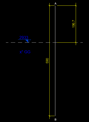
Question: I'm struggling to create a rebar dimension line because I can't find a way to get the edges of the element in a section view:
I can retrieve their edges through their geometry, but the edge I need doesn't have a reference that I can use.
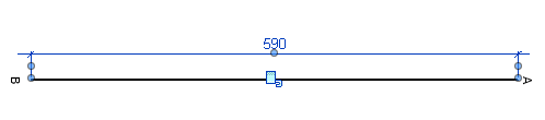
My ultimate goal is to measure the distance from the end of the bar to a level or grid:
Answer: Similar questions were raised here in the past, to:
The solutions back then include reading the element geometry and the references it provides, just like you describe:
You can read the geometry data from the rebar by
Rebar.Geometryproperty. This property requires anOptionargument. You need to set theoption.ComputeReferencesto true. Then read the edge of the rebar, and get the curve from theEdgeobject. Finally, get the end point reference from the curve.
Response: I already looked at these posts but with no results. When I create the dimension line, a reference is needed. The approach you describe returns a null reference for the edge.
Here are 4 different paths I attempted, with no desired result so far:
PLAN A:
  ReferenceArray ra = new ReferenceArray();
  Line dimension = Line.CreateBound(rebar_top, apoyo_top);
  DetailLine line1 = doc.Create.NewDetailCurve(view, dimension) as DetailLine;
  ra.Append(line1.GeometryCurve.GetEndPointReference(1));
  ra.Append(line1.GeometryCurve.GetEndPointReference(0));
  Dimension dim = doc.Create.NewDimension(doc.ActiveView, dimension, ra);
PLAN B:
  XYZ apoyo_top = pAnalisisSupCap + rle.cm_to_ft(200) * XYZ.BasisZ;
  XYZ apoyo_bot = pAnalisisSupCap - rle.cm_to_ft(200) * XYZ.BasisZ;
  XYZ rebar_top = pini + rle.cm_to_ft(200) * XYZ.BasisZ;
  XYZ rebar_bot = pini - rle.cm_to_ft(200) * XYZ.BasisZ;
  Line l_v = Line.CreateBound(apoyo_bot, apoyo_top);
  Line l_h = Line.CreateBound(rebar_bot, rebar_top);
  Plane p_h = Plane.CreateByNormalAndOrigin(rebar_bot
    .CrossProduct(rebar_top), rebar_top);
  SketchPlane skplane_h = SketchPlane.Create(doc, p_h);
  Plane p_v = Plane.CreateByNormalAndOrigin(apoyo_bot
    .CrossProduct(apoyo_top), apoyo_top);
  SketchPlane skplane_v = SketchPlane.Create(doc, p_v);
  ModelCurve modelcurve1 = doc.Create.NewModelCurve (l_h, skplane_h);
  ModelCurve modelcurve2 = doc.Create.NewModelCurve(l_v, skplane_v);
  ra.Append(modelcurve1.GeometryCurve.Reference);
  ra.Append(modelcurve2.GeometryCurve.Reference);
  ra.Append(modelcurve1.GeometryCurve.GetEndPointReference(0));
  ra.Append(modelcurve2.GeometryCurve.GetEndPointReference(0));
PLAN C:
  Options opt = new Options();
  opt.ComputeReferences = true;
  opt.View = doc.ActiveView;
  opt.IncludeNonVisibleObjects = true;
  GeometryElement geomElem = rebInt.get_Geometry(opt);

  foreach (GeometryObject geomObj in geomElem)
  {
    Solid geomSolid = geomObj as Solid;
    if (null != geomSolid)
    {
      int faces = 0;
      double totalArea = 0;
      foreach (Face geomFace in geomSolid.Faces)
      {
        faces++;
        faceInfo += "Face " + faces + " area: "
          + geomFace.Area.ToString() + "\n";
        totalArea += geomFace.Area;
        info = geomFace;
      }
      faceInfo += "Number of faces: " + faces + "\n";
      faceInfo += "Total area: " + totalArea.ToString() + "\n";

      int edge = 0;
      foreach (Edge geomEdge in geomSolid.Edges)
      {
        geoobj = geomEdge.AsCurve();
      }
    }
  }
  // No Faces/Edges valiuds as references.
PLAN D:
IListdd = rebInt .GetRebarConstraintsManager().GetAllHandles(); RebarConstrainedHandle s = null; RebarConstrainedHandle e = null; foreach (RebarConstrainedHandle rbh in dd) { if (rbh.GetHandleName().ToString() == "Start of Bar") { s = rbh; } if (rbh.GetHandleName().ToString() == "End of Bar") { e = rbh; } } // This objects (handles) doesn't give references.
Answer: I verified that your plan A throws an exception saying, 'The direction of dimension is invalid'.
This is because the input value dimension should lie inside the plan of doc.ActiveView.
So, I changed the input value dimension of the following code line to line1.GeometryCurve as Line.
It works, but you just need to offset Z of the dimension line to make it looks good:
  Dimension dim = doc.Create.NewDimension(
    doc.ActiveView, line1.GeometryCurve as Line, ra );
Answer and Solution: With the great support from our Revit engineering team, I got the ideal solution and verified that it works fine to dimension between rebar and grid.
The code contains a command that places a dimension in your model. You will need to select the rebar. The grid line is hard-coded by its element id.
It implements the following steps:
- Get all rebar references.
- Filter them to choose the one that we need.
- Get the grid reference.
- With the rebar ref and grid references, create the dimension.
If you want to only dimension the rebar, you just need to change the code to get the two references of the edges perpendicular to rebarSeg:
using System;
using System.Collections.Generic;
using Autodesk.Revit.DB;
using Autodesk.Revit.UI;
using Autodesk.Revit.UI.Selection;
using Autodesk.Revit.Attributes;
using Autodesk.Revit.DB.Structure;

namespace TestRebar
{
  [TransactionAttribute( TransactionMode.Manual )]
  public class TestRebar : IExternalCommand
  {
    UIApplication m_uiApp;
    Document m_doc;

    ElementId elementId = ElementId.InvalidElementId;

    public Result Execute(
      ExternalCommandData commandData,
      ref string message,
      ElementSet elements )
    {
      try
      {
        initStuff( commandData );
        if( m_doc == null )
          return Result.Failed;

        m_uiApp = commandData.Application;
        Selection sel = m_uiApp.ActiveUIDocument.Selection;
        Reference refr = sel.PickObject( ObjectType.Element );

        Rebar rebar = m_doc.GetElement( refr.ElementId ) as Rebar;

        Line rebarSeg = null;
        bool bOk = getRebarSegment( rebar, out rebarSeg );
        if( !bOk )
          return Result.Failed;

        Options options = new Options();
        // the view in which you want to place the dimension
        options.View = m_uiApp.ActiveUIDocument.ActiveView;
        options.ComputeReferences = true; // produce references
        options.IncludeNonVisibleObjects = true;
        GeometryElement wholeRebarGeometry
          = rebar.get_Geometry( options );
        Reference refForEndOfBar = getReferenceForEndOfBar(
          wholeRebarGeometry, rebarSeg );

        Reference refGrid = getGridRef();

        ReferenceArray refArray = new ReferenceArray();
        refArray.Append( refForEndOfBar );
        refArray.Append( refGrid );

        double dist = 10;

        // a line parallel with our rebar segment somewhere in space
        Line dimLine = rebarSeg.CreateOffset(
          dist, XYZ.BasisY ) as Line;

        using( Transaction tr = new Transaction( m_doc ) )
        {
          tr.Start( "Create Dimension" );
          m_doc.Create.NewDimension(
            m_uiApp.ActiveUIDocument.ActiveView,
            dimLine, refArray );
          tr.Commit();
        }
      }
      catch( Exception e )
      {
        TaskDialog.Show( "exception", e.Message );
        return Result.Failed;
      }

      return Result.Succeeded;
    }

    private Reference getGridRef()
    {
      ElementId idGrd = new ElementId( 397028 );
      Element elemGrid = m_doc.GetElement( idGrd );
      Options options = new Options();
      // the view in which you want to place the dimension
      options.View = m_uiApp.ActiveUIDocument.ActiveView;
      options.ComputeReferences = true; // produce references
      options.IncludeNonVisibleObjects = true;
      GeometryElement wholeGridGeometry
        = elemGrid.get_Geometry( options );
      IList<Reference> allRefs = new List<Reference>();
      foreach( GeometryObject geomObj in wholeGridGeometry )
      {
        Line refLine = geomObj as Line;
        if( refLine != null && refLine.Reference != null )
          return refLine.Reference;
      }

      return null;
    }

    private Reference getReferenceForEndOfBar(
      GeometryElement geom,
      Line rebarSeg )
    {
      foreach( GeometryObject geomObj in geom )
      {
        Solid sld = geomObj as Solid;
        if( sld != null )
        {
          // I'll get the references from curves;
          continue;
        }
        else
        {
          Line refLine = geomObj as Line;
          if( refLine != null && refLine.Reference != null )
          {
            // We found one reference.
            // Let's see if it is the correct one.
            // The correct referece need to be perpendicular
            // to rebar segement and the end point of rebar
            // segment should be on the reference curve.
            double dotProd = refLine.Direction.DotProduct(
              rebarSeg.Direction );
            if( Math.Abs( dotProd ) != 0 )
              continue; // curves are not perpendicular.

            XYZ endPointOfRebar = rebarSeg.GetEndPoint( 1 );
            IntersectionResult ir = refLine.Project(
              endPointOfRebar );
            if( ir == null )
              continue; // end point of rebar segment is not on the reference curve.

            if( Math.Abs( ir.Distance ) != 0 )
              continue; // end point of rebar segment is not on the reference curve.

            return refLine.Reference;
          }
        }
      }
      return null;
    }

    private bool getRebarSegment(
      Rebar rebar,
      out Line rebarSeg )
    {
      rebarSeg = null;
      IList<Curve> rebarSegments
        = rebar.GetCenterlineCurves( false, true, true,
        MultiplanarOption.IncludeOnlyPlanarCurves, 0 );
      if( rebarSegments.Count != 1 )
        return false;

      rebarSeg = rebarSegments[0] as Line;
      if( rebarSeg == null )
        return false;

      return true;
    }

    void initStuff( ExternalCommandData commandData )
    {
      m_uiApp = commandData.Application;
      m_doc = m_uiApp.ActiveUIDocument.Document;
    }
  }
}
Response: Thanks a lot for the response. It is the solution to our problem! We made little adjustments to the code to have plenty of control about what end do we want to dimension, and also we had to project all the curves involved into a shared reference plane due to the fact that if you have more than one rebar (rebar set), the geometry of the rebar is above or beneath the grid line.
Again, thanks a lot for your time and effort.
This thanks is due to Zhong (John) Wu, Boris Shafiro and especially Stefan Dobre.
Newly Created Dimensioning Not Displayed
For another issue or two, on newly created dimensioning not being displayed properly, Frank @Fair59 Aarssen once again comes to the rescue:
Fair59 says: The workaround for dimensions to model elements, is rather simple. Create a new Dimension, using the References from the non-visible dimension.
Linear Reference from Surface Filtering for All
In yet another visibility question, on new dimensions are not visible, Unknowz describes another interesting approach:
Question:
I continued to check my code and found an interesting point which is probably at the origin of the problem.
I use this to obtain a reference to theBiggestFace:
  PlanarFace planarFace = theBiggestFace as PlanarFace;
  Reference refer = planarFace.Reference;
This returns a Reference whose ElementReferenceType is REFERENCE_TYPE_SURFACE.
However, in my case (with the faces parallel to the view), the dimensioning will only work with REFERENCE_TYPE_LINEAR.
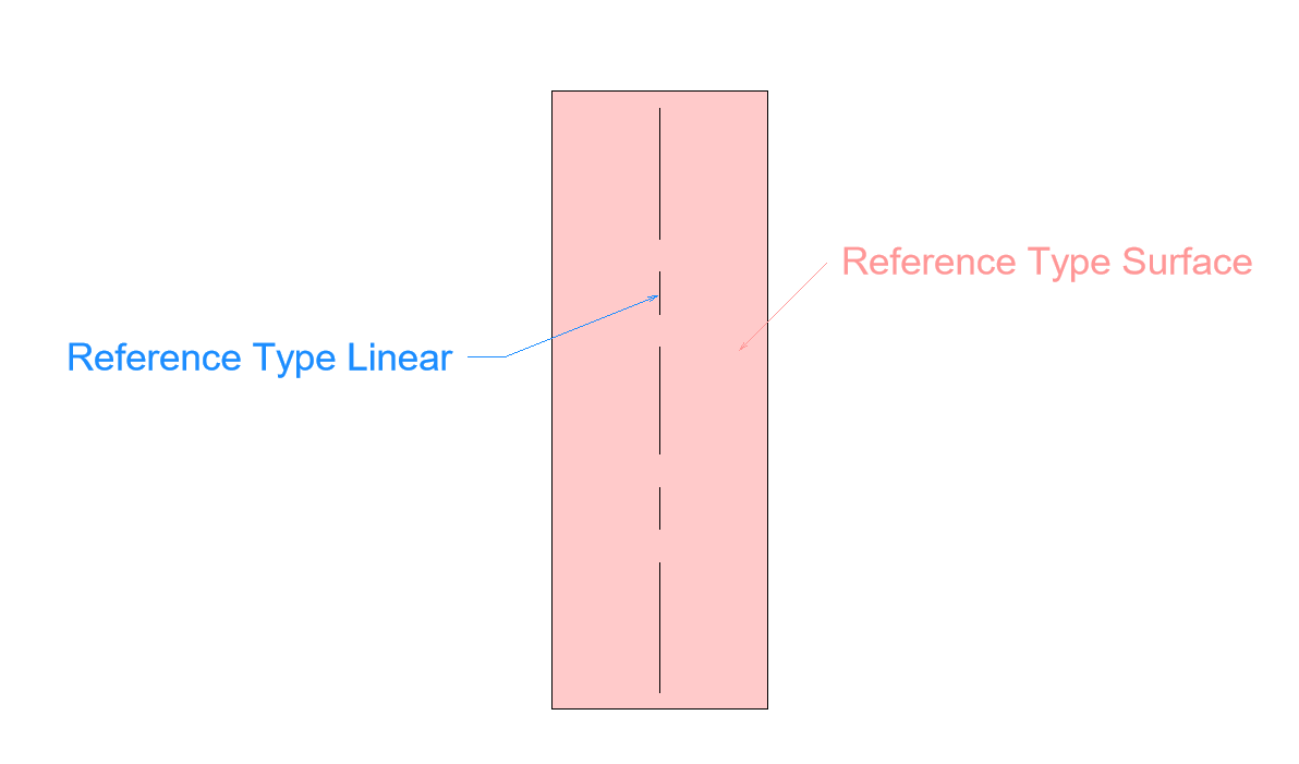
Do you have an idea of how to obtain a Reference with a type Linear from a Surface Reference?
It's probably a simple additional line at my existing code, but I couldn't find it yet...
Solution: Yes and No – I couldn’t properly find the reference line from the face, so now I do it another way.
I catch all the geometry objects from the view, both visible and invisible, and filter all these elements to find:
- A reference line parallel to the middle axis of the face
- The closest reference to the middle axis
It seems like a dirty solution, but it works, and, with good filtering, the performance stays acceptable.
Dimension Leader Remains Visible After Removal
Another dimensioning display issue that came up involves removing dimension leader not visible – only after reselection or reopening.
That was resolved by moving an element, as suggested in the bunch of examples illustrating the need to regenerate and various ways to achieve that:
doc.regenerateanduidoc.RefreshActiveViewdo not seem to do the trick.Your suggestion about moving the object is a good one.
Moving the dimension up and down within the same transaction (no need for two transactions) regenerates the dimension and removes the leaders.
  ElementTransformUtils.MoveElement( doc, dimRef.Id, XYZ.BasisZ );
  ElementTransformUtils.MoveElement( doc, dimRef.Id, -XYZ.BasisZ );
Dimension Wall Centreline, Centre and Faces of Core
A frequent requirement is to create dimension to wall centerline, center of core, faces of core
A lot of powerful and useful functionality addressing this was added in the Revit 2018 API, e.g.:
Fair59 added another solution to pinpoint specific core layers, e.g.:
- Overall Centre
- Core Exterior Face
- Core Interior Face
- Core Centre
- Exterior Wall Face
- Interior Wall Face
You can analyse the references of a dimension that measures the core using
Reference.ConvertToStableRepresentation.Using that information, you can then construct the references as follows:
  string format = "{0}:{1}:{2}";
  string uid = wall.uidId;
  int nines = -9999;

  refString = string.Format(format,uid,nines,1);
  Reference wall_centre = Reference
    .ParseFromStableRepresentation(doc,refString);

  refString = string.Format(format,uid,nines,2);
  Reference core_outer = Reference
    .ParseFromStableRepresentation(doc,refString);

  refString = string.Format(format,uid,nines,3);
  Reference core_inner = Reference
    .ParseFromStableRepresentation(doc,refString);

  refString = string.Format(format,uid,nines,4);
  Reference core_centre = Reference
    .ParseFromStableRepresentation(doc,refString);
Grid References for Dimensioning
Two other discussions deal with dimensioning grids:
One, on the failure to get reference for grid for dimension in 2017.
Alexander @aignatovich Ignatovich, aka Александр Игнатович solved it like this:
Instead of getting references from grid curves I used a reference to the entire grid element:
var gridRef = Reference.ParseFromStableRepresentation(doc, grid.UniqueId);
More solutions were presented for
using NewDimension between grids – invalid number of references, e.g.,
Richard Thomas suggested:
Basically, you can't use the reference from the curve of the grid (since that is a surface); you have to create a new reference by using the grid element itself:
New Reference(Grid). This reference you can then add to the reference array of theCreate.NewDimensionmethod. It's the same when dimensioning reference planes.If you only have the curve information to start with, you need to get the grid element from the curve's reference and then create a new reference from that.
THE
Create.NewDimensionmethod expects the reference type of a grid or reference plane to beREFERENCE_TYPE_NONE(for element), notREFERENCE_TYPE_SURFACE.
Simple, Better Grid References for Dimensioning
My colleague Jim Jia adds:
Please also look at the simple and better code to build reference for
Gridbelow; we don't need to retrieve reference fromGridgeometry. We verified that this works well:
  /// <summary>
  /// Return a reference built directly from grid
  /// </summary>
  Reference GetGridRef( Document doc )
  {
    ElementId idGrid = new ElementId( 397028 );
    Element eGrid = doc.GetElement( idGrid );
    return new Reference( eGrid );
  }