Edge Loop, Point Reference Plane and Column Line
A whole bunch of exciting Revit API topics to start the week:
- RevitLookup updated to use NuGet Revit API package
- Determining the outer-most
EdgeLoop - How to determine the location curve for a steel column
- Determining a reference plane from a reference point
- Beware of multiple outer loops
RevitLookup Updated to use NuGet Revit API Package
Andrey Bushman updated RevitLookup with pull request #36 to switch the target platform to .NET 4.6 and replace the Revit 2017 NuGet package by the Revit 2018.1 NuGet package.
Question: Why do you require .NET 4.6? This is not required by the Revit API, is it? Does the NuGet package need this?
Answer: Because I read about .NET 4.6 in the official Revit development requirements. They say: Revit's binaries are built using .NET 4.5.2. However, Revit uses the runtime from .NET 4.6.
Question: Why do you add so new Revit API DLL references? AdWindows, Macros, UIMacros, IFC...? Does the NuGet package need this? I prefer keeping RevitLookup as minimal as possible, for obvious reasons... I would prefer leaving the .NET version as required by Revit, and only reference the necessary Revit API DLLs.
Answer: These DLL references are automatically added by NuGet packages. The RevitAPI.dll and RevitAPIUI.dll libraries are used by Revit2018DevTools – this is one of my NuGet packages, it is used by Revit2018AddInTemplateSet templates.
Additional references don't take any space, and it is convenient when they are already added instead of requiring the programmer to add them each time manually. Creating a NuGet package for each DLL and then downloading each one separately is inconvenient and annoying for developers. I asked some of them about it. Therefore, they are the part of my NuGet packages.
Many thanks to Andrey for this update, included in RevitLookup 2018.0.0.3.
Determining the Outer-Most EdgeLoop
Richard Thomas shared a nice solution to the question raised in the Revit API discussion forum thread asking is the first EdgeLoop still the outer loop?
Question: I try to determine for all types of surfaces what is the outer EdgeLoop.
Is it always the first one returned by face.EdgeLoops?
If not, how to find it?
Answer: The Building Coder discussed how to determine 2D polygon areas and outer loop by area comparison.
Richard presents an alternative solution based on a simple max and min calculation. In his words:
The area approach mentioned there is probably more reliable, but I had an alternate idea based on getting all co-ordinates linked to the edge loops they are from and then finding the minimums in a certain direction. Below, I've taken min.x, but but same would apply for min.y, max.x and max.y.
I could not think of a situation where if you convert the 3D co-ordinates of each edge curve to a co-ordinate system of the plane you would end up with a min.x for the outer loop greater than the min.x for the inner loop. Similarly, the max.x of the outer loop should be greater than the max.x of the inner loop. This appeared to be true for most cases but then there was the issue of circular curves where the two end points could be further back than a point projecting into the centre of the curve. So, I decided to treat cyclic curves differently by checking for min.x along the curve.
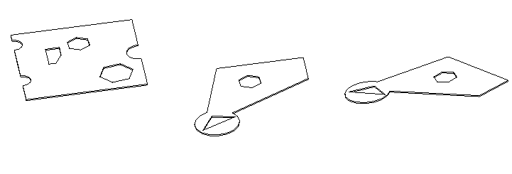
I came up with the two below functions, one for planar faces and the other for faces in general. They both seem to give reliable results on the cases in the image below (based on expected edge counts for the outer loops). However, there may be a case that fails. The parts related to co-ordinate transformations may need looking at (there may be better approaches). I checked the z of each transformed point to see that it was 0 or virtually 0, so seems to be as expected.
For the more generalised method I'm using API functionality which projects a point onto a face, I was expecting some possible intersection errors since I'm checking points on the boundary of the face. I've not checked such things in detail.
In summary, the area method mentioned in link is likely better and more reliable; not sure which is faster.
Public Shared Function Run(ByVal commandData As Autodesk.Revit.UI.ExternalCommandData) As Autodesk.Revit.UI.Result
  Dim IntApp As UIApplication = commandData.Application
  Dim IntUIDoc As UIDocument = IntApp.ActiveUIDocument
  If IntUIDoc Is Nothing Then Return Result.Failed Else
  Dim IntDoc As Document = IntUIDoc.Document

  Dim R As Reference = Nothing
  Try
    R = IntUIDoc.Selection.PickObject(Selection.ObjectType.Face)
  Catch ex As Exception
  End Try
  If R Is Nothing Then Return Result.Cancelled Else

  Dim F_El As Element = IntDoc.GetElement(R.ElementId)
  If F_El Is Nothing Then Return Result.Failed Else

  Dim F As Face = TryCast(F_El.GetGeometryObjectFromReference(R), Face)
  If F Is Nothing Then Return Result.Failed Else

  Dim EA1 As EdgeArray = PlannerFaceOuterLoop(F)
  Dim EA2 As EdgeArray = OuterLoop(F)

  Return Result.Succeeded
End Function

Public Shared Function OuterLoop(F As Face) As EdgeArray

  Dim MinU = Function(C As Curve) As Double

               If C.IsCyclic Then
                 Dim Min As Double = Double.NaN
                 For I = 0 To 20
                   Dim Param As Double = I / 20
                   Dim CuvPt As XYZ = C.Evaluate(Param, True)
                   Dim IR As IntersectionResult = F.Project(CuvPt)
                   If IR Is Nothing = False Then
                     If Min = Double.NaN Then
                       Min = IR.UVPoint.U
                     Else
                       If IR.UVPoint.U < Min Then
                         Min = IR.UVPoint.U
                       End If
                     End If
                   End If
                 Next
                 Return Min
               Else
                 Dim Pt1 As XYZ = C.GetEndPoint(0)
                 Dim Pt2 As XYZ = C.GetEndPoint(1)

                 Dim IR1 As IntersectionResult = F.Project(Pt1)
                 Dim IR2 As IntersectionResult = F.Project(Pt2)

                 If IR1 Is Nothing OrElse IR2 Is Nothing Then Return Double.NaN

                 If IR1.UVPoint.U < IR2.UVPoint.U Then
                   Return IR1.UVPoint.U
                 Else
                   Return IR2.UVPoint.U
                 End If
               End If
             End Function

  Dim Loops As IEnumerable(Of EdgeArray)
  Loops = From L As EdgeArray In F.EdgeLoops
          Select L

  Dim Cv As IEnumerable(Of Tuple(Of EdgeArray, Double))
  Cv = From L2 As EdgeArray In Loops
       From L3 As Edge In L2
       Let Mu As Double = MinU(L3.AsCurve)
       Where Mu <> Double.NaN
       Select New Tuple(Of EdgeArray, Double)(L2, Mu)


  Dim Out As Tuple(Of EdgeArray, Double) = Cv.ToList.Find(Function(Jx) Jx.Item2 = Cv.Min(Function(Jv) Jv.Item2))
  If Out Is Nothing Then
    Return Nothing
  Else
    Return Out.Item1
  End If
End Function

Public Shared Function PlannerFaceOuterLoop(F As Face) As EdgeArray
  Dim PF As PlanarFace = TryCast(F, PlanarFace)
  If PF Is Nothing Then Return Nothing Else

  Dim FN As XYZ = PF.FaceNormal
  Dim T As Transform = Transform.Identity
  T.BasisZ = FN
  T.BasisX = PF.XVector
  T.BasisY = PF.YVector
  T.Origin = PF.Origin

  'Dim Zeds As New List(Of Double)

  Dim MinU = Function(C As Curve) As Double
               If C.IsCyclic Then
                 Dim Min As Double = Nothing
                 For I = 0 To 20
                   Dim Param As Double = I / 20
                   Dim CuvPt As XYZ = C.Evaluate(Param, True)
                   Dim XYZt As XYZ = T.Inverse.OfPoint(CuvPt)
                   If I = 0 Then
                     Min = XYZt.X
                   Else
                     If XYZt.X < Min Then
                       Min = XYZt.X
                     End If
                   End If
                 Next
                 Return Min
               Else
                 Dim Pt1 As XYZ = C.GetEndPoint(0)
                 Dim Pt2 As XYZ = C.GetEndPoint(1)
                 Dim XYZp As XYZ() = New XYZ(1) {}

                 XYZp(0) = T.Inverse.OfPoint(Pt1)
                 XYZp(1) = T.Inverse.OfPoint(Pt2)

                 ' Zeds.Add(XYZp(0).Z)
                 ' Zeds.Add(XYZp(1).Z)

                 If XYZp(0).X < XYZp(1).X Then
                   Return XYZp(0).X
                 Else
                   Return XYZp(1).X
                 End If
               End If
             End Function

  Dim Loops As IEnumerable(Of EdgeArray)
  Loops = From L As EdgeArray In F.EdgeLoops
          Select L

  Dim Cv As IEnumerable(Of Tuple(Of EdgeArray, Double))
  Cv = From L2 As EdgeArray In Loops
       From L3 As Edge In L2
       Let Mu As Double = MinU(L3.AsCurve)
       Select New Tuple(Of EdgeArray, Double)(L2, Mu)


  Dim Out As Tuple(Of EdgeArray, Double) = Cv.ToList.Find(Function(Jx) Jx.Item2 = Cv.Min(Function(Jv) Jv.Item2))
  If Out Is Nothing Then
    Return Nothing
  Else
    Return Out.Item1
  End If
End Function
I like Richard's idea, so I rewrote his functions in C# and added them to The Building Coder samples.
Instead of using C.Evaluate twenty times over, I call the curve Tessellate method. That also handles the case of a linear curve gracefully, returning just the two end points, so the MinU function can be shortened and simplified:
public static double MinU( Curve C, Face F )
{
  return C.Tessellate()
    .Select<XYZ, IntersectionResult>( p => F.Project( p ) )
    .Min<IntersectionResult>( ir => ir.UVPoint.U );
}

public static double MinX( Curve C, Transform Tinv )
{
  return C.Tessellate()
    .Select<XYZ, XYZ>( p => Tinv.OfPoint( p ) )
    .Min<XYZ>( p => p.X );
}

public static EdgeArray OuterLoop( Face F )
{
  EdgeArray eaMin = null;
  EdgeArrayArray loops = F.EdgeLoops;
  double uMin = double.MaxValue;
  foreach( EdgeArray a in loops )
  {
    double uMin2 = double.MaxValue;
    foreach( Edge e in a )
    {
      double min = MinU( e.AsCurve(), F );
      if( min < uMin2 ) { uMin2 = min; }
    }
    if( uMin2 < uMin )
    {
      uMin = uMin2;
      eaMin = a;
    }
  }
  return eaMin;
}

public static EdgeArray PlanarFaceOuterLoop( Face F )
{
  PlanarFace face = F as PlanarFace;
  if( face == null )
  {
    return null;
  }
  Transform T = Transform.Identity;
  T.BasisZ = face.FaceNormal;
  T.BasisX = face.XVector;
  T.BasisY = face.YVector;
  T.Origin = face.Origin;
  Transform Tinv = T.Inverse;

  EdgeArray eaMin = null;
  EdgeArrayArray loops = F.EdgeLoops;
  double uMin = double.MaxValue;
  foreach( EdgeArray a in loops )
  {
    double uMin2 = double.MaxValue;
    foreach( Edge e in a )
    {
      double min = MinX( e.AsCurve(), Tinv );
      if( min < uMin2 ) { uMin2 = min; }
    }
    if( uMin2 < uMin )
    {
      uMin = uMin2;
      eaMin = a;
    }
  }
  return eaMin;
}
I added them to The Building Coder samples release 2018.0.134.3 module CmdSlabBoundaryArea.cs L29-L102.
Many thanks to Richard for implementing, testing and sharing this simple approach!
How to Determine the Location Curve for a Steel Column
Richard also answered another Revit API discussion forum thread on retrieving the location curve of a steel column:
Question: How can I get the location curve for a steel member column?
Answer: When searching for an answer to a question like this, you should always start by first checking the examples provided by the official Revit SDK and the developer guide. I count 58 occurrences of LocationCurve in the SDK samples. The Building Coder also includes 64 different examples of accessing the LocationCurve of an element.
However, there are some twists involved specifically with steel columns, so this is a trick question.
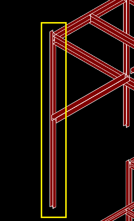
A vertical column will have a location point and no curve at all.
Furthermore, its Z component will be zero, regardless what level it resides on.
A slanted column, on the other hand, is equipped with a location curve.
For vertical columns, you can derive end points via level parameters and offsets. Getting such information is not generally as easy as just getting a location curve. It follows the below procedure:
Check what type of column you are dealing with via SLANTED_COLUMN_TYPE_PARAM (Int32); it takes its value from the SlantedOrVerticalColumnType enumeration.
Determine the start and end level elements from:
FAMILY_TOP_LEVEL_PARAM(ElementID)FAMILY_BASE_LEVEL_PARAM(ElementID)
Consider the Elevation or ProjectElevation parameters of those level elements (depending on need).
Determine the offsets of the column ends from the corresponding levels via:
FAMILY_BASE_LEVEL_OFFSET_PARAM(Double)FAMILY_TOP_LEVEL_OFFSET_PARAM(Double)
Add those to the numerical level of each end.
Alternatively, change SLANTED_COLUMN_TYPE_PARAM from 0 to 1 or 2, which stands for angle driven and endpoint driven. Then, the column becomes equipped with a location curve and you can extract information from that.
I favour the first longer approach because it is purely reading the database, not transacting with it.
The above-mentioned built-in parameters have changed for consistency; older versions of Revit use ones specific to columns. Check the API documentation for details on this.
Finally, for the sake of completeness, here are previous discussions by The Building Coder on some aspects of slanted columns that illuminate further:
Determining a Reference Plane from a Reference Point
Last but not least, another very useful and illuminating solution that deserves mentioning is from Fair59, once again, in the Revit API discussion forum thread on obtaining a reference plane from reference point:
Question: In the Revit family environment, I am drawing two reference points RefArrPts and drawing a reference line crv that connects the two points. In the next step, I extract the reference points from the reference line CrvRefPts. In the last step, I try to extract the XY plane plnRef from the reference points CrvRefPts. The returned value is of type REFERENCE, the element id of plnRef is the same element id of the CrvStRefPt. The method GetCoordinatePlaneReferenceXY states that it returns a reference to the XY plane of the coordinate system, but it is returning a reference to the point instead.
  CurveByPoints crv = RvtDoc.FamilyCreate
    .NewCurveByPoints( RefArrPts );

  crv.IsReferenceLine = true;
  ReferencePointArray CrvRefPts = crv.GetPoints();
  ReferencePoint CrvStRefPt = CrvRefPts.get_Item( 0 );
  plnRef = CrvStRefPt.GetCoordinatePlaneReferenceXY();
What am I doing wrong? Any guidance would be greatly appreciated.
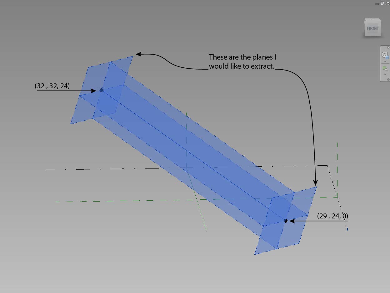
The line I am drawing is not orthogonal; therefore, I need to extract the plane from the curve end points so that the plane is perpendicular to the line. If I extract the plane from the original two points, I will get planes orthogonal to the world coordinates, which is not useful to me.
The reason for extracting these planes is to draw geometry on them (via the API) and then allow the user to move the line and have the constrained geometry update.
The steps the user would execute are as follows:
- Run a command that draws the line and the geometry on the reference planes.
- Move the line as desired within the model; all geometry will update.
Answer: You can easily generate pure geometric planes yourself like this:
  XYZ p1 = first point
  XYZ q2 = second point
  XYZ v = p2 - p1
  XYZ normal = v.Normalise
  Plane plane1 = Plane.Create( p1, normal )
  Plane plane2 = Plane.Create( p2, normal )
If you require a reference to an existing plane element in the model, you could search all of them for one with a matching origin and normal vector.
The planes you are after are faces of the solid of the reference line, the solid returned by crv.get_geometry. Unfortunately, they don't have a reference. If you require a reference to host the geometry, then you'd have to host two extra reference points on the reference line and use the references from those.
  ReferencePoint rPnt0 = null;
  ReferencePoint rPnt1 = null;
  using( SubTransaction st = new SubTransaction( doc ) )
  {
    st.Start();
    PointLocationOnCurve location
      = new PointLocationOnCurve(
        PointOnCurveMeasurementType.NormalizedCurveParameter,
        0, PointOnCurveMeasureFrom.Beginning );

    PointOnEdge pointOnEdge = doc.Application.Create
      .NewPointOnEdge( crv.GeometryCurve.Reference,
      location );

    rPnt0 = doc.FamilyCreate.NewReferencePoint(
      pointOnEdge );

    location = new PointLocationOnCurve(
      PointOnCurveMeasurementType.NormalizedCurveParameter,
      1, PointOnCurveMeasureFrom.Beginning );

    pointOnEdge = doc.Application.Create.NewPointOnEdge(
      crv.GeometryCurve.Reference, location );

    rPnt1 = doc.FamilyCreate.NewReferencePoint(
      pointOnEdge );

    st.Commit();
  }
  ReferencePointArray CrvRefPts
    = new ReferencePointArray();

  CrvRefPts.Append( rPnt0 );
  CrvRefPts.Append( rPnt1 );

  ReferencePoint CrvStRefPt = CrvRefPts.get_Item( 0 );
  plnRef = CrvStRefPt.GetCoordinatePlaneReferenceYZ();
Many thanks to Fair59 for explaining this and sharing the solution!
Beware of Multiple Outer Loops
Adrian Esdaile added a warning in his comment below that you should definitely be aware of:
In reference to the question about Outer loops: Unfortunately, the quirky nature of Revit will defeat you here. It is entire possible to create valid geometry in Revit composed of TWO (yes, TWO, or more...) OUTER loops. How this will behave with your code (or indeed ANY code!) is questionable.
For example – create a Floor in Sketch mode, create two 'islands' of floor, click OK... done! Revit calls this ONE floor object, but it's clearly TWO separate pieces – that behave as one. It is considered VERY POOR DRAFTING to create floors like this; but "users gonna use" if you give them a chance, and it's a quick and lazy way of doing things.
In a perfect world, Revit would slap you with an error for trying to create a daft and confusing object like this; but this world (and Revit, bless its binary heart) is far from perfect.
For an example of unimaginably bad practice in Revit drafting (but very common in the field, dammit...) See this example file I call – floors_of_unimaginable_evil.rvt:
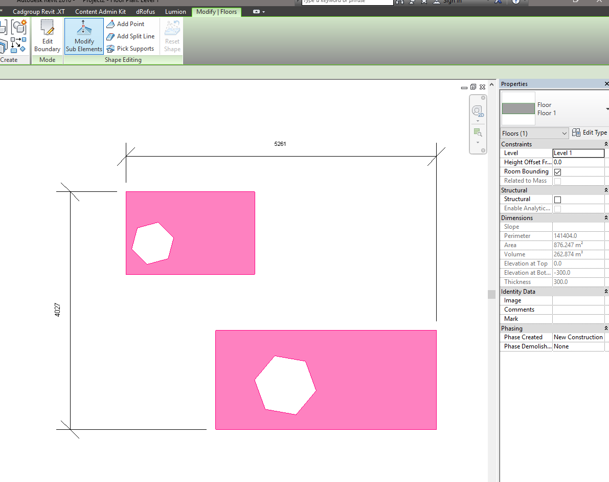
Look at the image above – there is something terribly wrong with the area reported for this floor... and what about the volume...? Huh? Why would someone do that? Doesn't matter why, but "users gonna use" as I said – if Revit allows it, users WILL do it! RVT 2016 format, by the way. Feel free to use this file as a test case for 'what can happen' :-D
Yes, I've used a Floor in this example, but Revit is not consistent in when it will or won't allow multiple curves to count as single curve. I suspect you can do this with columns, too, as a column might be defined by a swept blend... which greatly expands the possibilities for evil.
Response: Obviously, it is not that hard to test whether a Revit so-called edge loop consists of multiple disjoint loops, but it places substantial additional burden on the programmer.
My preferred way to deal with this (or at least protect myself as an add-in developer) would be to implement a reliable model checking algorithm, run automatically at regular intervals as well as before saving the BIM project, that checks for and warns about weird user input of this kind.
Obviously, the number of creative and involuntarily evil things that users can get up to is absolutely unlimited, so the number of checks performed would grow with time as new evil possibilities are discovered and discouraged.