SDK Update, RvtSamples and Setting Grid Endpoint
An updated version of the Revit SDK was published, I set up RvtSamples for Revit 2018, which I use to
load The Building Coder samples,
and we present a useful employment of the DatumPlane class methods GetCurvesInView and SetCurveInView:
Revit 2018 SDK Update
An update of the Revit SDK has been posted to the Revit Developer Centre:
- Revit 2018 SDK (Update May 19, 2017) (msi - 355088Kb)
It includes the new DuplicateGraphics sample that was omitted in the first customer shipment of the Revit 2018 SDK.
RvtSamples for Revit 2018
I use the Revit SDK external application RvtSamples to load all the SDK samples for testing and debugging purposes.
I first described it in The Building Coder's fifth blog post on Managing SDK Samples.
I soon implemented the include file functionality to also use it to load all other sample commands that I regularly use, including The Building Coder samples.
Last year, Dan Tartaglia raised and I addressed several issues setting up RvtSamples for Revit 2017.
This year, I went through a similar process.
For the sake of efficiency, I am here simply posting the entire contents of my RvtSamples folder as it stands now, up and running on my system.
The only files that I modified are:
- Application.cs
- RvtSamples.addin
- RvtSamples.txt

Now to return to the topic for today:
How to Modify Grid Curve End Points
Question: I would like to modify end points of a grid curve for 3D extent, but the Grid.Curve property is read-only, so I cannot set a new curve.
Is there any way to edit a grid curve?
Answer: Ever since Revit 2016, the Grid class provides the methods GetCurvesInView and `SetCurveInView.
More precisely, these methods were added to the DatumPlane class, which is a base class of Grid.
GetCurvesInView retrieves a collection of curves representing a DatumPlane element in a given view:
  public IList<Curve> GetCurvesInView(
    DatumExtentType extentMode,
    View view
  )
They can be set using SetCurveInView:
  public void SetCurveInView(
    DatumExtentType extentMode,
    View view,
    Curve curve
  )
The DatumExtentType specifies what type of datum extent that is displayed in a particular view.
If you want the actual 3D extents, you need to pass in DatumExtentType.Model.
After retrieving the current grid curves, you can determine their end points, create a new line using those points, and set it back to the grid via Grid.SetCurveInView.
Here is code snippet demonstrating this:
UIApplication uiapp = commandData.Application;
UIDocument uidoc = uiapp.ActiveUIDocument;
Document doc = uidoc.Document;
Selection sel = uidoc.Selection;
View view = doc.ActiveView;

ISelectionFilter f
  = new JtElementsOfClassSelectionFilter<Grid>();

Reference elemRef = sel.PickObject(
  ObjectType.Element, f, "Pick a grid" );

Grid grid = doc.GetElement( elemRef ) as Grid;

IList<Curve> gridCurves = grid.GetCurvesInView(
  DatumExtentType.Model, view );

using( Transaction tx = new Transaction( doc ) )
{
  tx.Start( "Modify Grid Endpoints" );

  foreach( Curve c in gridCurves )
  {
    XYZ start = c.GetEndPoint( 0 );
    XYZ end = c.GetEndPoint( 1 );

    XYZ newStart = start + 10 * XYZ.BasisY;
    XYZ newEnd = end - 10 * XYZ.BasisY;

    Line newLine = Line.CreateBound( newStart, newEnd );

    grid.SetCurveInView(
      DatumExtentType.Model, view, newLine );
  }
  tx.Commit();
}
Many thanks to Ryuji Ogasawara for sharing this!
There is hardly any error checking here, so you need to know exactly what to pick.
It moves the grid endpoints vertically, so you need to select a vertically oriented grid for it to work.
I added Ryuji's sample as a new external command to The Building Coder samples release 2018.0.133.0 in the module CmdSetGridEndpoint.cs.
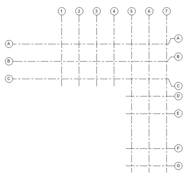
Here are the isolated grids in rac_basic_sample.rvt:

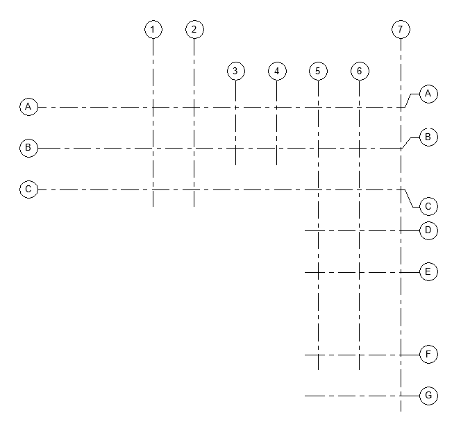
Launching CmdSetGridEndpoint and picking 3, 4, 5 and 6 generates this:
