Bounding Box Solid and Forge Webinar
Yesterday I submitted the handout for my presentation on connecting the desktop and cloud for the RTC Revit Technology Conference Europe in Porto next month.
I still have to finish my work on the roomedit3dv3 sample
to demonstrate connecting the desktop with the cloud by enabling a real-time round-trip modification of the BIM via the Forge viewer;
yesterday I integrated the transform viewer extension;
now I have to hook up the socket.io messaging back to the Revit add-in to update the BIM.
Meanwhile, let's pick up a nice little geometric Revit API topic and mention the recording from the latest Forge webinar session:
Create Solid from Bounding Box
Owen Merrick provides a very nice sample add-in in the Revit API discussion forum thread on creating a solid from a bounding box:
Question: I have a bounding box and want to convert in to a solid;
one possible solution is to use CreateExtrusionGeometry using a curve loop from some lines created from its bounding box.
Is there a better solution to accomplish this?
For now, I used CreateExtrusionGeometry and it is OK, but I would appreciate a better solution if one exists.
Answer: Do you want to generate a persistent Revit database element?
If so, the simplest solution is almost certainly to use a DirectShape element.
Response: In my case, this solid is a temporary one to use with ElementIntersectsSolidFilter.
Since the intersecting element is a brace, I can't use BoundingBoxIntersectsFilter.
If the Revit API would offer a gradient bounding box, that could be of great use for elements such as braces.
Answer: I was looking for an approach to address the very same question, ended up here, and re-created your solution.
To save the next person a bit of typing, here is my code:
 <summary>
/// Create and return a solid representing
/// the bounding box of the input solid.
/// Assumption: aligned with Z axis.
/// Written, described and tested by Owen Merrick for
/// http://forums.autodesk.com/t5/revit-api-forum/create-solid-from-boundingbox/m-p/6592486
/// </summary>
public static Solid CreateSolidFromBoundingBox(
  Solid inputSolid )
{
  BoundingBoxXYZ bbox = inputSolid.GetBoundingBox();

  // Corners in BBox coords

  XYZ pt0 = new XYZ( bbox.Min.X, bbox.Min.Y, bbox.Min.Z );
  XYZ pt1 = new XYZ( bbox.Max.X, bbox.Min.Y, bbox.Min.Z );
  XYZ pt2 = new XYZ( bbox.Max.X, bbox.Max.Y, bbox.Min.Z );
  XYZ pt3 = new XYZ( bbox.Min.X, bbox.Max.Y, bbox.Min.Z );

  // Edges in BBox coords

  Line edge0 = Line.CreateBound( pt0, pt1 );
  Line edge1 = Line.CreateBound( pt1, pt2 );
  Line edge2 = Line.CreateBound( pt2, pt3 );
  Line edge3 = Line.CreateBound( pt3, pt0 );

  // Create loop, still in BBox coords

  List<Curve> edges = new List<Curve>();
  edges.Add( edge0 );
  edges.Add( edge1 );
  edges.Add( edge2 );
  edges.Add( edge3 );

  double height = bbox.Max.Z - bbox.Min.Z;

  CurveLoop baseLoop = CurveLoop.Create( edges );

  List<CurveLoop> loopList = new List<CurveLoop>();
  loopList.Add( baseLoop );

  Solid preTransformBox = GeometryCreationUtilities
    .CreateExtrusionGeometry( loopList, XYZ.BasisZ,
      height );

  Solid transformBox = SolidUtils.CreateTransformed(
    preTransformBox, bbox.Transform );

  return transformBox;
}
I'd love a more elegant answer, but this works for my needs.
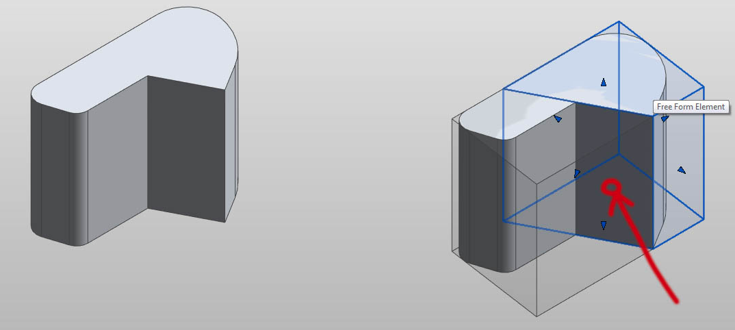
Upon selecting the planar face of a solid, two new solids are created: the two halves of the bounding box of the original, split by the plane of the selected face.
Here is sampleSplitBoundingBox.zip containing an external command showing a simplified version of how I'm using the bounding box code.
Whether this command meets the definition of 'doing something handy' is debatable, but it's at least a functional command.
I'm working on solid modelling tools for working with non-parametric masses using somewhat different formal logic than the built-in "form" tools. The step demonstrated here is really just one piece of construction geometry on the way to a more complex, yet-unfinished tool, but it illustrates a few useful functions:
- From user face selection, retrieve both the face and the solid.
- From solid, generate solid of bounding box.
- Insert solid into family context.
This draws very heavily on the sample code provided with the Revit SDK, particularly the FreeFormElement sample and planar face selection filter.
For the sample code I copied the relevant bits into a fresh add-in and zipped the whole thing up. This includes the source, working .dll, sample image and rfa in the doc folder.
Response: As a use case, we use very similar code to do interference checking within a provided tolerance.
I think you nailed it and I don't think there is a more elegant solution.
Many thanks to Owen for sharing this solution and putting together such a nice reproducible case to demonstrate it in action!
I added CreateSolidFromBoundingBox as a new utility method
to The Building Coder samples
release 2017.0.130.2 in
the module Util.cs,
with these diffs to the previous release.
Forge Webinar Series 4 – Viewer
Jaime Rosales Duque presented the fourth session in the ongoing Forge webinar series, on the Viewer.
Recordings, presentations and support material of all past sessions are available for viewing and download:
- September 20 – Introduction to Autodesk Forge and the Autodesk App Store
- September 22 – Introduction to OAuth and Data Management API – on OAuth and Data Management API, providing token-based authentication, authorization and a unified and consistent way to access data across A360, Fusion 360, and the Object Storage Service.
- September 27 – Introduction to Model Derivative API – on the Model Derivative API that enables users to represent and share their designs in different formats and extract metadata.
- September 29 – Introduction to Viewer – the Viewer, formerly part of the 'View and Data API', is a WebGL-based JavaScript library for 3D and 2D model rendering of CAD models from seed files, e.g., AutoCAD, Fusion 360, Revit and many other formats.
Upcoming sessions continue during the remainder of the Autodesk App Store Forge and Fusion 360 Hackathon until the end of October:
- October 4 – Design Automation API – formerly known as 'AutoCAD I/O', run scripts on design files.
- October 6 – BIM360 – develop apps that integrate with BIM 360 to extend its capabilities in the construction ecosystem.
- October 11 – Fusion 360 Client API – an integrated CAD, CAM, and CAE tool for product development, built for the new ways products are designed and made.
- October 13 – Q&A on all APIs.
- October 20 – Q&A on all APIs.
- October 27 – Submitting a web service app to Autodesk App store.
Quick access links:
- For API keys, go to developer.autodesk.com
- For code samples, go to github.com/Developer-Autodesk
Feel free to contact us at forgehackathon@autodesk.com at any time with any questions.