Voodoo Magic Retrieves Global Instance Edges
I recently shared Scott Wilson's reference stable representation magic voodoo, and you may have asked yourself what use it is.
Well, here is one example making effective use of it, raised and solved by Ola Gunnar Skippervik of Multiconsult, one of the leading firms of consulting engineers and designers in Norway.
- Goal: retrieve family instance edge to create direct shape
- Snooping the family instance geometry
- Answer
- Confirmation
- Summary
- Structural concrete setout point add-in
Goal: Retrieve Family Instance Edge to Create Direct Shape
I have been programing on an add-on for Revit for my company over some time now. One function that I am trying to implement is to create setout lines (separate objects that can during export to DWG be placed on separate layers).
The workflow that I have tried to implement is as follows:
- Select edges
- Extract the Curve from the Edge
- Use
WireframeBuilderto create aDirectShapefrom the curves
What I just experienced was that for some structural foundations (it is the same family type the is used for all of my instances) this code is for some of my instances producing a direct shape with the global geometry of the foundation, and sometimes it is reading the local geometry in my structural foundation, causing the Direct shape to be inserted near the project basepoint.
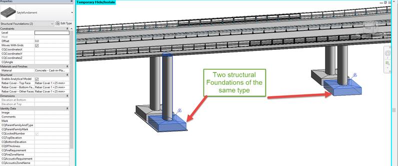
Here are two structural foundations of the same type:
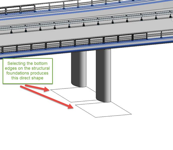
Retrieving some of their bottom edges produces the desired direct shape:
On other instances, retrieving their bottom edges produces a direct shape at the project base point instead:
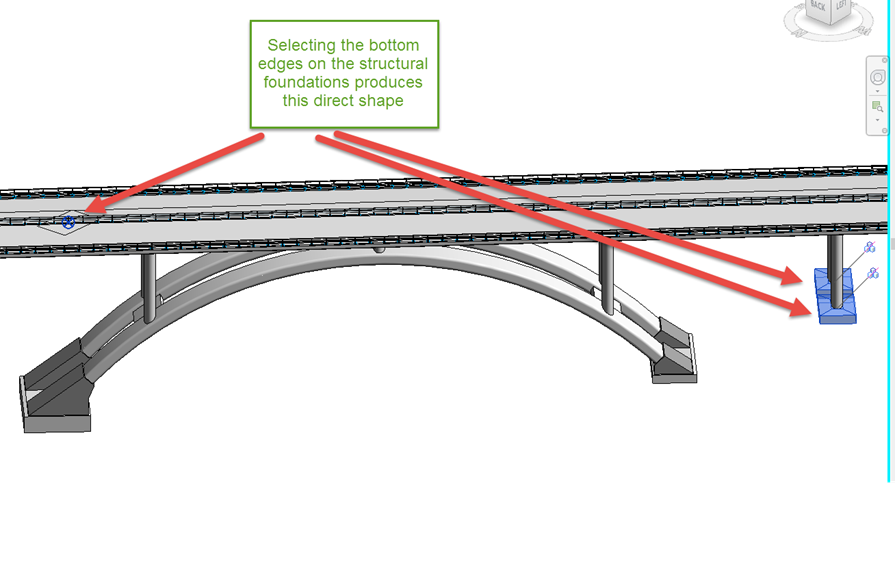
Obviously, the family instance geometry is sometimes retrieved in global project coordinates, and sometimes in local family definition coordinates.
Q1: How can I be sure to always get the global geometry to put into the DirectShape?
Q2: Can you please point me in the right direction when I wish to select the Edge of a curved surface that is joined tangentially with the next surface (also to be used in the same manner as described above)?
Snooping the Family Instance Geometry
I’ve been snooping two objects that produce different behaviour. This is what I found so far:
The family instances on which I can retrieve the global geometry have direct geometry objects:
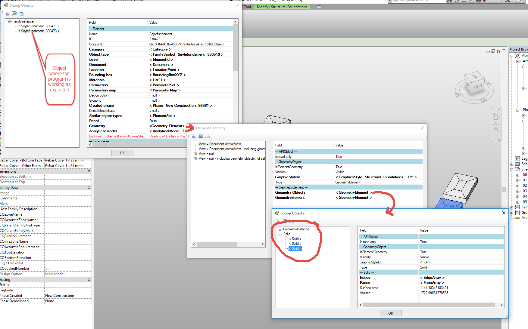
The other ones have geometry instances, from which the geometry objects have to be retrieved in a second step:
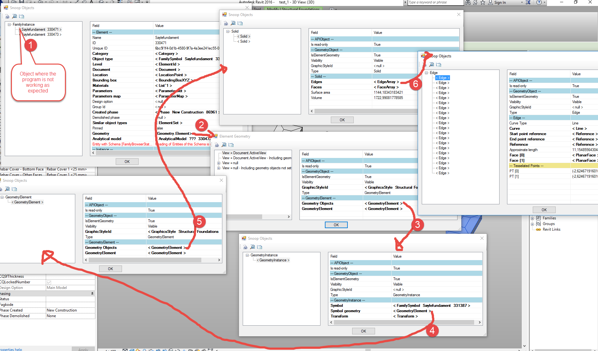
The problematic geometry seems to be nested deeper in the latter element. Why so? If I copy the element that behaves as I expected, the new element also works fine. If I add a new instance (place structural foundation or create similar) the new instance the element gets the nested properties.
Q3: Why are the elements built up differently?
Q4: How can I implement a solution that produces geometry at the globally same place as I picked the edge?
Answer
Some family instances can make use of the unmodified symbol geometry generated by the family definition.
In that case, they can obtain their geometry from the GeometryInstance object, and share it with other instances.
In other cases, the geometry may need some modification for a specific instance, so it cannot be shared.
In that case, the instance generates its own geometry.
The discussion on
GetInstanceGeometry Overhead and Invalid References points out some differences between the GetSymbolGeometry and GetInstanceGeometry methods that can be used to access these different geometry collections.
Other developers have encountered similar problems in the past distinguishing between local and global coordinated retrieved from family instances, as you can see from the Revit API discussion forum thread on converting local family instance coordinate of selected edge to project coordinates.
In it, Scott Wilson provides a solution making use of some reference stable representation magic voodoo.
Might that come in useful for you too?
Later, I noticed that I encountered and solved this exact same problem myself in a more direct and offical manner without the use of any voodoo magic for my structural concrete setout point add-in discussed below.
Confirmation
Thank you!
I implemented the GetInstanceEdgeFromSymbolRef method suggested by the Voodoo Magic, and everything works like a charm!
This was something that I would not be able to come up with myself.
Once again, thank you! You saved the day!
Summary
What I wanted the add-in to do was the following:
- Let the user select some edges in the model (typical some characteristic edges on the structure, to be used for generating set-out data/lines for the contractor when exported to dwg or dxf).
- Create a new geometry object that can represent the set-out data (lines)
This is done by:
- Extract edges
- Get the Curves form the edges
- Add curves to
WireframeBuilder - Add the geometry from the wireframe builder to a direct shape
What I experienced was that for some instances I got the global geometry, and for other I got the local geometry. This caused some serious headache, because after some time I understood that I had to use GetGeometryInstance to collect the whole bunch of geometry from the element, but then I had no clue how to find the right curve corresponding to the selected edge. This was fixed by the method GetInstanceEdgeFromSymbolRef.
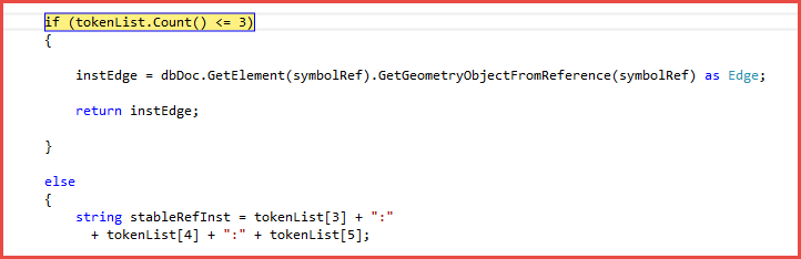
However, when I selected an edge on an element where the geometry was stored directly in the element, the method cast an error due to the fact that the tokenList count was only 3, not 6 as for the others.
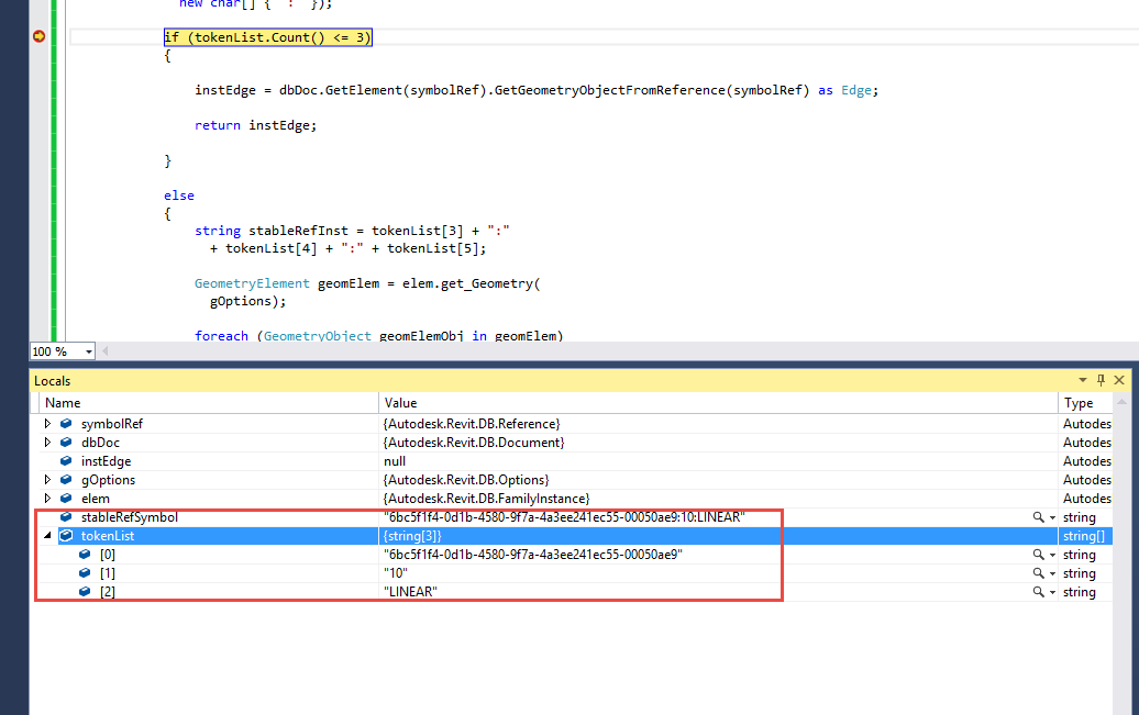
My solution to this was to add an if test for the count of the tokenList to the method:
I hope this proves useful for others as well!
Many thanks to Ola Gunnar for his useful sample and confirmation!
Structural Concrete Setout Point Add-In
By the way, talking about set-out geometry, I once implemented a full-fledged structural concrete setout point add-in, later migrated to Revit 2015 and hosted in the GitHub SetoutPoints repository.
It is a Revit add-in for automatic placement and management of structural concrete setout points.
Here is some more on its history:
- Melbourne DevLab
- Commercial use of the SetoutPoints application
- Revit API forum discussion thread on Jeremy's SetoutPoints
In the forum discussion, the exact same issue as above is raised and solved to ensure that all points are placed correctly in the global coordinate system using a more direct and officially supported approach without any voodoo magic :-)
Now it just remains to compare the two approaches and determine which is better, simpler and more reliable.