Using Routing Preferences to Select and Place a Tap
Today, I address a sequence of Revit MEP related steps required to insert a specific tap or take-off fitting into a duct:
- How to determine duct face from location point?
- How to convert
XYZlocation to duct faceUVcoordinates? - How to anchor an object like AutoCAD Architecture?
- How to inherit system information?
- How to inherit system information – take II
- How to control take-off and tap sizing on a duct?
- How to select a specific tap type to connect to a duct?
- Sample code using routing preferences to select
NewTakeOffFittingtap type
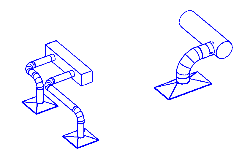
The final result of this exploration is sample code snippet that makes use of routing preferences to select the appropriate take-off fitting type, a very frequently asked question, and produces taps like this:
This issue was raised and all the research performed by Michael Hillis of DrawTech, Inc.
Many thanks to Michael for his perseverance and especially for sharing the final solution with us all!
How to Determine Duct Face from Location Point?
I have a duct fitting family with a tap family (or take-off, if you prefer). Along with this, I also have a location point for the tap. The location point is the point at which the tap intersects with and rests upon the tap. It is my assumption that to correctly place this tap family to my duct fitting family, I need to place the tap on the applicable Face on my duct fitting family. I have a couple of questions about performing this.
Using my location point, what would be the simplest method to retrieve the face that point rests upon?
Would that be using the EdgeArrayArray method?
Answer
Regarding your first question, that is pretty easy to achieve.
I would suggest retrieving the element geometry, iterating over all its faces, projecting the XYZ point onto each one, and determining the distance between the original and the projected result.
Here are some early examples from The Building Coder where I played at those kind of games:
- RayTraceBounce Pool Table
- Rectangular Duct Corners
- Spot Elevation Creation on Top of Beam
- Dimension Walls by Iterating Faces
The second post demonstrates a method called FaceContainsConnector that might suit your needs.
The fourth implements GetClosestFace, which takes the face normal vector into account as well as the target point.
How to Convert XYZ Location to Duct Face UV Coordinates?
Once I have that face, is there any means within the API to get the UV point of the face based on its XYZ location within the project?
Answer
Regarding the second question, retrieving the UV point on the face for a given XYZ point:
Yes, absolutely the API provides that.
Look at the Face.Project method, which projects the specified input XYZ point onto the face.
It returns an IntersectionResult that includes a UVPoint property with the 2D parameters of the point of intersection in the face coordinate system.
For one of many examples of using this method in context, please take a look at the method PlaceFamilyInstanceOnFace provided in The Building Coder discussion
on determining the face tangent at a picked point by generic face tangent determination.
Please note that this face analysis and the nitty-gritty details of XYZ and UV coordinates are not utilised at all in the final solution using the PreferredJunctionMethod described below. We will simply keep these sections in place for narrative purposes, since these are the steps we investigated to make it happen.
How to Anchor an Object Like AutoCAD Architecture?
Thank you for the quick reply and the wealth of information! Your resources are great for getting the actual tap onto my object.
However, I do have another question to pose:
I hate to draw a comparison to AutoCAD, but it's the only way I know how to really convey what I'm looking for. In AutoCAD, you have something called Anchoring objects. This basically allows you to take one object and make it a slave to another object. Think of the relationship between a tap and the duct it is attached to. The tap will always be fixed to that duct, go wherever it goes, etc.
I'm looking for something like this in Revit and was hoping you could confirm if I am on the right track before I spend a lot of time down this avenue.
Does this also handle inheritance of duct system information?
Answer
The AutoCAD ObjectARX anchor functionality only ensures a geometrical relationship. It does not care about duct system information.
That can be achieved using the Revit API Dynamic Model Updater framework DMU.
Look specifically at the Associative Section View SDK sample for an example of geometric anchoring of an object to another.
No, this does not have anything whatsoever to do with handling inheritance of duct system information, and neither does the AutoCAD Architecture Anchor system.
How to Inherit System Information?
OK. I'm looking for a method to attach a tap to a duct fitting and have that tap inherit the fittings information, e.g., things like System Name, Classification, etc. Much like what happens when you connect ducts together using connectors.
Answer
Regarding the inheritance of fitting information, dimensions, like duct and pipe diameter, width, height, system name, classification, etc.:
That is managed by the Revit duct and pipe system itself.
All MEP elements are assigned to a system, belong to that system, and inherit that kind of information from the system they belong to.
You mention connecting ducts together using connectors; yes.
In Revit, the fittings are also equipped with connectors, just like the ducts, and the information conveyed between them is exactly the same, using the exact same mechanism; namely, they all belong to the same MEP system.
How to Inherit System Information – Take II
Now, back to the second matter. I have two separate families, both custom objects, one is a piece of rectangular duct and the other is a tap object. When I attach the tap to the face of this duct object, it adheres in a geometric sense as it should, however; it does not get any System Information from the duct object. That's what I need now. Is there any possible way to achieve that?
The goal is that my tap receives the system information from the main duct body.
Answer
Yes, the transmission of the system information can be easily resolved.
Your tap has a connector, and so does the duct.
You need to connect the two connectors with each other.
Of course, being a tap, it will not hook up to the standard pre-defined duct connectors at the end points, but somewhere along the walls, in the middle somewhere.
There is a special mechanism for adding additional connectors for such cases.
You might have to create that situation manually and analyse the results.
Explore the differences generated by manually adding taps to a duct using RevitLookup, the BipChecker, element lister and other database exploration tools.
Use that understanding to reproduce the same programmatically.
You may need to use the right overload of the NewFamilyInstance method to place the tap on the duct and generate a new connector for it.
Actually, maybe the Document.NewTakeoffFitting method is what you need to use:
Let's see, what more do I have to offer on taps?
How to Control Take-Off and Tap Sizing on a Duct?
So I've been looking at this and have decided my approach has been wrong on this particular matter from the start. As opposed to using a Duct Fitting Family for each individual Duct Joint Length, I'm now using an actual Duct object (the Revit base) and splitting it to represent the joint lengths. This feature is a god send.
Now I have my take-off/tap, and am attaching it to my duct object and that seems to work.
However, when I set a family to Tap – Adjustable or Tap – Perpendicular, I cannot change any of its sizing dimensions such as Width, Depth and Diameter.
How does one change these dimensions?
I need to be able to insert a Rect/Oval tap with any combination of Width and Depth values.
Answer
I'm glad to hear that you made progress and the initial issue is now resolved.
Regarding the sizing dimensions: I think the sizing dimensions are properties of the system or the duct run, not the individual duct itself.
You might therefore need to modify them one level higher up in the hierarchy.
How do you do it in the user interface?
How is that reflected in the element properties that you explore using RevitLookup?
That should immediately answer your question.
How to Select a Specific Tap Type to Connect to a Duct?
I think I have a solid grasp on the way TakeOffs and Duct objects work now at least from a User Interface perspective. My question:
Using the API, is there a way to insert a particular type of tap onto a piece of duct and connect it to a duct?
Looking at the NewTakeOffFitting method, it takes an MEPCurve and a connector, both of which I can supply, but the TakeOff I'm inserting has to be of a particular type, which usually isn't completely static. I'll need to be able to insert a Bevelled, Straight or Custom (one that I have created) take-off on a whim when I need to.
It seems my best avenue for being able to insert Taps more 'on-the-fly' based on whatever I'm importing via my add-in is utilizing the RoutingPreferencesManager within the MEPCurve that I am trying to attach my duct to.
I have a basic idea of what is going on here, but I've run into a little bit of an issue. It seems that the take-off fittings I'm looking to utilize aren't showing up when I list all of the available 'rules' within a given RuleGroup (in this case, Junctions). For example, using the Revit UI (not the API) if I load a take-off family into my project using the "Load Family.." routine in Revit, it will show that take-off fitting if I go and manually modify the Routing Preferences within the UI.
However, if I do the same thing in the API, I can't get the tap that I'm loading to show up. Even if I manually load the tap in my project before running the add-in. I can't actually see the Tap as an available rule.
Here is a code sample snippet of what I am doing:
  // I start with my Duct (with MEPCurve).

  Element ductElement = MyDuctElement;

  Duct duct = null;
  if( ductElement != null )
  { duct = MyDuctElement; }

  FamilySymbol tapSym = null;

  // Load my Take-Off family.

  using( SubTransaction subTrans = new SubTransaction( doc ) )
  {
    subTrans.Start();

    // Load the tap FamilySymbol into the project.

    GetFamilySymbolRoutine( doc, symInfo, out famSym );

    subTrans.Commit();
  }

  DuctType ductType = duct.DuctType;

  type.RoutingPreferenceManager.PreferredJunctionType
    = PreferredJunctionType.Tap;

  int ruleCount = ductType
    .RoutingPreferenceManager
    .GetNumberOfRules(
      RoutingPreferenceRuleGroupType.Junctions );

  // Iterate through all rules within Junctions
  // and get part info for all rules.

  List<string> names = new List<string>();
  RoutingPreferenceRule routeRule = null;

  for( int i = 0; i < ruleCount; i++ )
  {
    routeRule = ductType
      .RoutingPreferenceManager.GetRule(
        RoutingPreferenceRuleGroup, i );

    Element mepId = doc.GetElement(
      routeRule.MEPPartId );

    if( mepId != null )
    {
      FamilySymbol mepFi = mepId as FamilySymbol;
      names.Add( mepFi.Name );
    }
  }
Do you have any resources or tips that might assist me in fully utilizing the RoutingPreferenceManager?
Answer
Yes, routing preferences is definitely the way to go.
The tap needs to be explicitly added to the routing preferences.
Loading the family alone does not add the rule.
This is similar to the UI approach: after loading the family, the part needs to be added to the rule in another operation.
The API could look like this:
  RoutingPreferenceRule newRule( tapFamilySymbolId,
    "Something about this rule" );

  myRoutingPreferenceManager.AddRule(
    RoutingPreferenceRuleGroupType.Junctions, newRule );
You can find more routing preference API usage examples in the RoutingPreferenceTools Revit SDK sample.
Sample Code Using Routing Preferences to Select NewTakeOffFitting Tap Type
I made progress on the issue and arrive at a solution similar to the set-up the development team recommends.
Here is another code snippet showing the general gist of what I'm currently utilizing:
  // Get DuctType - we need this for its
  // RoutingPreferenceManager. This is how we assign
  // our tap object to be used. This is the settings
  // for the duct object we attach our tap to.

  Duct duct = doc.GetElement( mainDuctId );

  DuctType ductType = duct.DuctType;

  RoutingPreferenceManager routePrefManager
    = ductType.RoutingPreferenceManager;

  // Set Junction Prefernce to Tap.

  routePrefManager.PreferredJunctionType
    = PreferredJunctionType.Tap;

  // For simplicity sake, I remove all previous rules
  // for taps so I can just add what I want here.
  // This will probably vary.

  int initRuleCount = routePrefManager.GetNumberOfRules(
    RoutingPreferenceRuleGroupType.Junctions );

  for( int i = 0; i != initRuleCount; ++i )
  {
    routePrefManager.RemoveRule(
      RoutingPreferenceRuleGroupType.Junctions, 0 );
  }

  // Get FamilySymbol for Tap I want to use.

  FamilySymbol tapSym = null;
  doc.LoadFamilySymbol( "C:\FamilyLocation\MyTap.rfa",
    "MyTap", out tapSym );

  // Symbol needs to be activated before use.

  if( ( !tapSym.IsActive ) && ( tapSym != null ) )
  {
    tapSym.Activate();
    doc.Regenerate();
  }

  // Create Rule that utilizes the Tap. Use the argument
  // MEPPartId = ElementId for the desired FamilySymbol.

  RoutingPreferenceRule newRule
    = new RoutingPreferenceRule( tapSym.Id, "MyTap" );

  routePrefManager.AddRule(
    RoutingPreferenceRuleGroupType.Junctions, newRule );

  // To create a solid tap, we need to use the Revit
  // doc.Create.NewTakeoffFitting routine. For this,
  // we need a connector. If we don't have one, we
  // just create a temporary object with a connector
  // where we want it.

  Connector tmpConn = CreateTemporaryConnectorForTap();

  // Create our tap.

  FamilyInstance tapInst
    = doc.Create.NewTakeoffFitting( tmpConn, duct );
I put this together really quickly for you, but I think it covers all the bases.
I've found that this solution works extremely well for creating a tap that utilizes the standard features Revit has for taps, producing results like the two samples shown above.
Thank you for all your support!