IFC Import Levels and MEP Element Shapes
I answered far too many threads on the Revit API discussion forum in the past few days to list them all, so I'll just pick out two cases of special interest today:
Levels Generated by IFC Import
Here is a little detail to watch out when importing an IFC file: Revit may generate a level for you automatically under certain circumstances.
This issue was raised by David Robison, Design Master Electrical RT, in the discussion thread on IFC import – level line is automatically created:
Question: I have an IFC file to be imported into Revit. When it is imported, a level line at 0 m is included in each elevation. I can turn this off in each elevation manually. Is there a way to suppress it automatically?
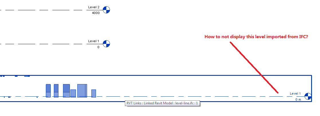
Answer: Here is the discussion we had on this with the development team:
[Q] Is there any automated way to remove or disable the level added in elevation view by the IFC import?
[A] Revit needs at least one building story. This file doesn’t seem to have any levels in it, so it is creating a default one. This seems to be standard behaviour.
[Q] Does that mean there is no way to automatically disable the default level display? Should I file a wish for it?
[A] I don’t think it would make much sense to make a wish for this. There has to be a level in a Revit file, and default view templates show levels. I might not fully understand his issue, but I am not sure exactly what the wish list item would be.
[Q] The reason it that several levels already exist in the current project, especially there is a “Level 1”. When IFC is imported, it creates another “Level 1” with 0 m elevation, which is redundant.
[A] OK, I think I see the issue here.
In general, we expect IFC files to have at least one building story in them. If they don’t, we’ll create one.
If they do, we will reuse the Level 1 already existing in the template to avoid exactly the case below. In this case, though, because we are creating a level – not reading one from the IFC file – we don’t do the matching that we’d normally do.
The workaround is simple: add a Level 1 to the IFC file.
We'll deal better with the case where there are no levels in the IFC file in the future.
Determining MEP Duct and Pipe Element Shape
This is an old topic that has been discussed several times in the past, brought up again in the Revit API discussion forum thread on how to get duct shape.
In the past, we also spent some effort on solving it.
The solution now is really simple, since the introduction of the ElementType.FamilyName property in the Revit 2015 API:
Question: 有没有简单的办法直接获得风管的DuctShape?
我知道接口可以获得shape
There is no simple way to directly get Duct Shape Duct?
I know it can be obtained in the user interface.
Answer: You are asking how to determine the cross sectional shape of a duct element.
This used to be a pretty hard question, once upon a time, and several different approaches could be taken, e.g. geometrical analysis, as you can see from these previous discussions:
Another way to achieve this is to open the duct fitting family and query the DuctConnector element for its Shape property, as explained by Joe Ye in how to get the duct section shape for duct type object.
Unfortunately, opening the family is quite a costly operation.
From Revit 2015 onwards, the simplest an most effective method to achieve what you need is to query the ElementType.FamilyName property.
In your case, that might look like this:
  /// <summary>
  /// Determine element shape from its
  /// element type's family name property.
  /// </summary>
  static public string GetElementShape4(
    Element e )
  {
    string shape = "unknown";

    ElementId tid = e.GetTypeId();

    if( ElementId.InvalidElementId != tid )
    {
      Document doc = e.Document;

      ElementType etyp = doc.GetElement( tid )
        as ElementType;

      if( null != etyp )
      {
        shape = etyp.FamilyName;
      }
    }
    return shape;
  }
I added this code to The Building Coder samples release 2016.0.126.3, in the module CmdMepElementShape.cs, in lines 721-745.
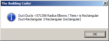
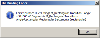
Here is the result of a test run on the first two elements in this sequence of rectangular ducts and transitions:

Selecting the left-most duct:
Selecting the transition in the middle:
Charles Piro chimed in to the discussion and suggested querying the shape of each duct connector like this:
  /// <summary>
  /// Return shape of first end connector on given duct.
  /// </summary>
  public ConnectorProfileType GetShape( Duct duct )
  {
    ConnectorProfileType ductShape
      = ConnectorProfileType.Invalid;

    foreach( Connector c
      in duct.ConnectorManager.Connectors )
    {
      if( c.ConnectorType == ConnectorType.End )
      {
        ductShape = c.Shape;
        break;
      }
    }
    return ductShape;
  }
I modified that to return the shapes of all duct connectors like this:
  /// <summary>
  /// Return shape of all duct connectors.
  /// </summary>
  static ConnectorProfileType[] GetProfileTypes(
    Duct duct )
  {
    ConnectorSet connectors
      = duct.ConnectorManager.Connectors;

    int n = connectors.Size;

    ConnectorProfileType[] profileTypes
      = new ConnectorProfileType[n];

    int i = 0;

    foreach( Connector c in connectors )
    {
      profileTypes[i++] = c.Shape;
    }
    return profileTypes;
  }
Reporting the result of this method as well produces the following on the first rectangular duct, informing us of the shapes of the duct itself as well as all its connectors:
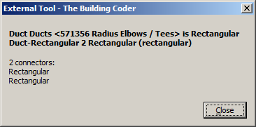
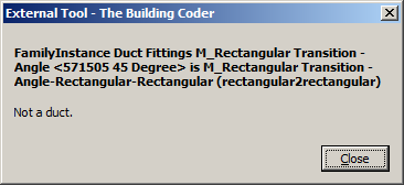
The result for the transition is basically the same as before; since it is not a duct, its connectors are not accessed:
Of course, you can very easily enhance the GetProfileTypes method to handle other MEP element types as well besides ducts.
That is left as an exercise to the reader :-)
The updated The Building Coder samples release 2016.0.126.4 includes Charles' suggestion as well.