Create Duct, Pipe and Point Transform
Our topics for today are on creating ducts, pipes and transforming a point:
I am writing this from the village Agii Apostoli on the east side of the Greek island of Euboea, on my way to the second I love 3D – Athens meetup on June 5, followed by the AngelHack hackathon on June 6-7. For more details, please refer to The 3D Web Coder.
Creating Specific Ducts and Pipes
Question: I am just getting started working with the Revit MEP API.
I would like to create a 'normal' pipe or duct, or, more specifically, use a fitting to represent a piece of pipe.
Is this possible?
None of the existing duct or pipe fittings that I can find seem usable for this purpose.
Answer: In Revit, pipes and ducts make use of built-in system types.
You cannot use standard family definitions read in from external sources such as RFA files.
Of course, you can duplicate and modify the system types to adapt them for your needs.
You can certainly implement your own family to represent a straight piece of piping or ductwork, and probably even make it work, to a certain extent.
However: That would probably be a really bad idea.
You should probably make use of the built-in system pipe and duct types, or you will be working against the system, fighting it, instead of working with it.
You can modify the pipe and duct type properties to match your needs, you know.
If you don't like the geometry that Revit uses to represent it, you can even implement your own alternative geometry representation using direct shapes.
Are you sure you have fully explored the Revit MEP optimal workflow and best practices?
For an example of creating complete connected systems of pipes, ducts and fittings, please refer to the AutoRoute and AvoidObstruction Revit SDK samples.
They have been mentioned by The Building Coder numerous times, mostly in connection with other related samples at the same time.
One example that I spent quite a lot of time researching and implementing fully is the rolling offset:
- Calculating a Rolling Offset Between Two Pipes
- Creating a Rolling Offset Pipe Between Two Pipes
- Connecting the Rolling Offset Pipe to its Neighbour Pipes
- Explicitly Placing Rolling Offset Elbow Fittings
That should show you all there is to know about this topic.
All that I know, anyway.
I hope this helps.
Good luck making the right choices!
How to use Transform.CreateRotationAtPoint
Raised by Redsky in the Revit API discussion forum thread on figuring out how Transform.CreateRotationAtPoint works:
Question: I am trying to take an XYZ point and rotate it by 1 Pi (180 degrees) around another base point. I think I got the correct method but I cannot figure out how to use it. See this image:
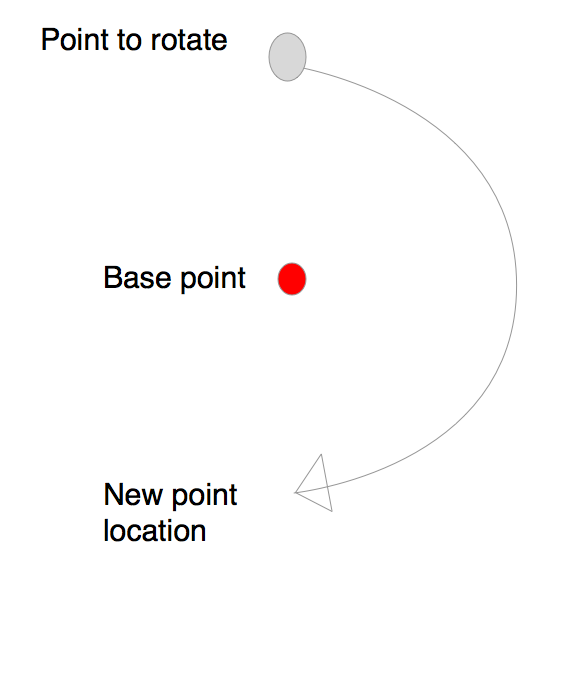
Is the base point equal to the XYZ Origin? Is the base point considered the origin? I think so...
How do I define the AXIS using an XYZ? Does anyone have an image to explain this? I couldn't find any documentation. I want to rotate the point along the XY plane (in plan orientation).
The angle is in Radians, I got that one.
  Transform t = Transform.CreateRotationAtPoint(
    new XYZ( Origin.X, Origin.Y, Origin.Z + 1 ),
    Math.Pi, Origin );

  t.whatMethodHereToGetNewXYZLocationOfPoint?
Once I get the transform, how do I get the new XYZ location of my rotated point?
Thanks.
Answer: The Transform.CreateRotation method creates a rotation transformation given just two arguments, the rotation axis and angle.
CreateRotationAtPoint takes three arguments: the axis, rotation angle and base point.
Here is one short description of how not to use CreateRotationAtPoint :-)
To define an axis by an XYZ, simply consider the XYZ a vector instead of a point.
Your attempt to define the axis looks like a mixture between a point and a vector to me; you have added the axis you need, the Z axis vector, to the base point. Good try, but no cigar.
In your case, to determine the rotation of the point pOld to the result pNew by 180 degrees around the base point base_point in the XY plane, i.e., around the Z axis, you can do this:
  XYZ axis = XYZ.BasisZ;
  double angle = Math.PI;
  Transform t = Transform.CreateRotationAtPoint(
    axis, angle, base_point );
  XYZ pNew = t.OfPoint( pOld );