Exporting 3D Element Geometry to a WebGL Viewer
Yesterday, I discussed how to get started with WebGL and demonstrated a simple 3D viewer making use of the Tiny WebGL helper Library TWGL.
Today, I present the TwglExport Revit add-in to select an individual element and populate the viewer with that.
To drive the WebGL viewer, we just need a bunch of vertex locations, normal vectors in each vertex, and face definitions hooking them up with each other.
TwglExport achieves exactly that though the following steps:
- Retrieve the pre-selected element.
- Determine its bounding box and geometry.
- Loop through the geometry objects, ignoring everything except solids.
- Loop through the solid faces.
- For each face, request a triangulated mesh.
- For each mesh triangle, export its three corners and its normals at each one.
- Add the indices of the resulting vertex and normal coordinate entries to the face definition list.
I already implemented a number of similar algorithms and add-ins in the past, e.g., the OBJ model exporter and the ADN mesh data custom exporter to JSON.
Please be aware that for most serious uses, you will wish to export multiple elements that may have a complicated nested geometric structure, e.g. family instances, or an entire building model.
In those cases, you will almost certainly save a lot of effort by making use of a custom exporter instead of traversing individual element geometry like I am doing here for this trivial single-element case.
The element geometry that I retrieve from the Revit database is all in feet.
For the sake of simplicity and efficiency – and maybe show the imperialists that I am in control here :-) – I convert it to the revolutionary and republican metric millimetres – Liberté, égalité, fraternité!
In case you were not aware of it, the metric system was introduced during the French Revolution, by the French First Republic, in 1799.
I also find that having my geometric data in integers instead of real numbers makes it much easier to read and understand while debugging.
Furthermore, I translate it all from the midpoint of the selected element's bounding box to the origin.
Right at the end of the process, I convert it back to real numbers again to fit it into a unit cube – actually a 2-cube from -1 to 1 in all three dimensions – centred around the origin.
Here is the entire code of the read-only TwglExport external command that achieves all this:
[Transaction( TransactionMode.ReadOnly )]
public class Command : IExternalCommand
{
  /// <summary>
  /// If true, individual curved surface facets are
  /// retained, otherwise (default) smoothing is
  /// applied.
  /// </summary>
  static public bool RetainCurvedSurfaceFacets = false;

  // Unit conversion factors.

  const double _mm_per_inch = 25.4;
  const double _inch_per_foot = 12;
  const double _foot_to_mm = _inch_per_foot * _mm_per_inch;

  /// <summary>
  /// Convert the given value from
  /// imperial feet to metric millimetres.
  /// </summary>
  static int FootToMm( double a )
  {
    double one_half = a > 0 ? 0.5 : -0.5;
    return (int) (a * _foot_to_mm + one_half);
  }

  /// <summary>
  /// Return the maximum absolute coordinate
  /// of the given point or vector.
  /// </summary>
  static double MaxCoord( XYZ a )
  {
    double d = Math.Abs( a.X );
    d = Math.Max( d, Math.Abs( a.Y ) );
    d = Math.Max( d, Math.Abs( a.Z ) );
    return d;
  }

  public Result Execute(
    ExternalCommandData commandData,
    ref string message,
    ElementSet elements )
  {
    UIApplication uiapp = commandData.Application;
    UIDocument uidoc = uiapp.ActiveUIDocument;
    Document doc = uidoc.Document;
    Selection sel = uidoc.Selection;
    ICollection<ElementId> ids = sel.GetElementIds();

    if( 1 != ids.Count )
    {
      message = "Please select an element to export to TWGL.";
      return Result.Failed;
    }

    Element e = null;

    foreach( ElementId id in ids )
    {
      e = doc.GetElement( id );
    }

    // Determine bounding box in order to translate
    // all coordinates to bounding box midpoint.

    BoundingBoxXYZ bb = e.get_BoundingBox( null );
    XYZ pmin = bb.Min;
    XYZ pmax = bb.Max;
    XYZ vsize = pmax - pmin;
    XYZ pmid = pmin + 0.5 * vsize;

    Options opt = new Options();
    GeometryElement geo = e.get_Geometry( opt );

    List<int> faceIndices = new List<int>();
    List<int> faceVertices = new List<int>();
    List<double> faceNormals = new List<double>();
    int[] triangleIndices = new int[3];
    XYZ[] triangleCorners = new XYZ[3];

    foreach( GeometryObject obj in geo )
    {
      Solid solid = obj as Solid;

      if( solid != null && 0 < solid.Faces.Size )
      {
        faceIndices.Clear();
        faceVertices.Clear();
        faceNormals.Clear();

        foreach( Face face in solid.Faces )
        {
          Mesh mesh = face.Triangulate();

          int nTriangles = mesh.NumTriangles;

          IList<XYZ> vertices = mesh.Vertices;

          int nVertices = vertices.Count;

          List<int> vertexCoordsMm = new List<int>( 3 * nVertices );

          // A vertex may be reused several times with
          // different normals for different faces, so
          // we cannot precalculate normals per vertex.
          //List<double> normals = new List<double>( 3 * nVertices );

          foreach( XYZ v in vertices )
          {
            // Translate the entire element geometry
            // to the bounding box midpoint and scale
            // to metric millimetres.

            XYZ p = v - pmid;

            vertexCoordsMm.Add( FootToMm( p.X ) );
            vertexCoordsMm.Add( FootToMm( p.Y ) );
            vertexCoordsMm.Add( FootToMm( p.Z ) );
          }

          for( int i = 0; i < nTriangles; ++i )
          {
            MeshTriangle triangle = mesh.get_Triangle( i );

            for( int j = 0; j < 3; ++j )
            {
              int k = (int) triangle.get_Index( j );
              triangleIndices[j] = k;
              triangleCorners[j] = vertices[k];
            }

            // Calculate constant triangle facet normal.

            XYZ v = triangleCorners[1]
              - triangleCorners[0];
            XYZ w = triangleCorners[2]
              - triangleCorners[0];
            XYZ triangleNormal = v
              .CrossProduct( w )
              .Normalize();

            for( int j = 0; j < 3; ++j )
            {
              int nFaceVertices = faceVertices.Count;

              Debug.Assert( nFaceVertices.Equals( faceNormals.Count ),
                "expected equal number of face vertex and normal coordinates" );

              faceIndices.Add( nFaceVertices / 3 );

              int i3 = triangleIndices[j] * 3;

              // Rotate the X, Y and Z directions,
              // since the Z direction points upward
              // in Revit as opposed to sideways or
              // outwards or forwards in WebGL.

              faceVertices.Add( vertexCoordsMm[i3 + 1] );
              faceVertices.Add( vertexCoordsMm[i3 + 2] );
              faceVertices.Add( vertexCoordsMm[i3] );

              if( RetainCurvedSurfaceFacets )
              {
                faceNormals.Add( triangleNormal.Y );
                faceNormals.Add( triangleNormal.Z );
                faceNormals.Add( triangleNormal.X );
              }
              else
              {
                UV uv = face.Project(
                  triangleCorners[j] ).UVPoint;

                XYZ normal = face.ComputeNormal( uv );

                faceNormals.Add( normal.Y );
                faceNormals.Add( normal.Z );
                faceNormals.Add( normal.X );
              }
            }
          }
        }

        // Scale the vertices to a [-1,1] cube
        // centered around the origin. Translation
        // to the origin was already performed above.

        double scale = 2.0 / FootToMm( MaxCoord( vsize ) );

        Debug.Print( "position: [{0}],",
          string.Join( ", ",
            faceVertices.ConvertAll<string>(
              i => ( i * scale ).ToString( "0.##" ) ) ) );

        Debug.Print( "normal: [{0}],",
          string.Join( ", ",
            faceNormals.ConvertAll<string>(
              f => f.ToString( "0.##" ) ) ) );

        Debug.Print( "indices: [{0}],",
          string.Join( ", ",
            faceIndices.ConvertAll<string>(
              i => i.ToString() ) ) );
      }
    }
    return Result.Succeeded;
  }
}
It also includes a smoothing option controlled by the setting of the Boolean RetainCurvedSurfaceFacets variable that defines whether curved faces display each of their individual facets or appear as one single nice and smooth organic surface.
I tested this on the model recently submitted by Alexander to test the curved wall elevation profile and creator class enhancements:
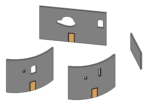
From it, I picked three walls of the four for testing, one of them in two flavours:
- Simple wall with no openings
- Straight wall with a funny cloud-shaped window
- Curved wall with a rounded window, faceted
- Curved wall with a rounded window, smooth
Here is the result, enabling you to choose between these four options – click 'Render' to begin and when you switch your wall selection:
Please be my guest and feel perfectly free to explore how this TWGL-based WebGL viewer is implemented by viewing the HTML and JavaScript source code of this page.
The entire TwglExport source code, Visual Studio solution and add-in manifest are provided in the TwglExport GitHub repository, and the version presented here is release 2015.0.0.1.
I'll dive into more detail and make this functionality available as a node.js web server anon, in happy cooperation with the getting started series that I am putting together on The 3D Web Coder.
Stay tuned...