Curved Wall Elevation Profile and Creator Class Update
Alexander Ignatovich, Александр Игнатович, of Investicionnaya Venchurnaya Companiya, took another and deeper look at The Building Coder sample external command CmdWallProfile that I originally implemented in 2008 to retrieve the wall elevation profile and my colleague Katsuaki Takamizawa modified to use the ExporterIFCUtils.SortCurveLoops method to sort the outer and inner loops a few months ago.
Alexander already made a number of other important contributions to The Building Coder in the past:
- Exporting Image and Setting a Default 3D View Orientation
- Intimate Revit Database Exploration with the Python Shell
- Multi-Version Visual Studio Revit Add-In Wizard
- Another Balloon Tip Implementation
- Category Analysis with and without Python
- WPF Fill Pattern Viewer Control
- Getting Serious Adding New Materials from List
- Accessing Extensible Storage on OwnerFamily in Project
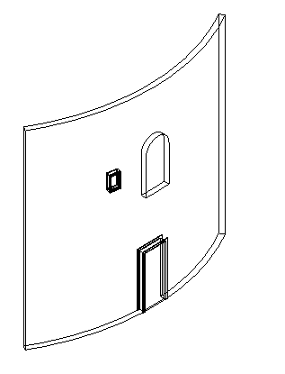
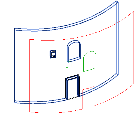
His improvement of the wall elevation profile command supports more complicated curves, such as the one generated by an arced window hosted by a cylindrical wall.
The results generated by unwrapping curves from cylinders and cones can become quite complicated and are not representable by the planar Revit API curve types.
Here is Alexander's analysis and description of his enhancements to support the case of an arced window in a cylindrical wall:
- Issues and task at hand
- First attempt
- Second attempt
- Final solution
- Python implementation
- Complete external command
- CreateModelLine clean-up
- Download
Issues and Task at Hand
You wrote about Wall elevation profiles in The Building Coder Samples in January and I was faced practically with the same task now.
Unfortunately, I could not get a wall profile for a wall whose Location curve is not a line, with neither the Execute1 nor Execute2 method from the sample, so it made me to go deeper and create my own implementation. I want to share this with the community.
The first thing I noticed: there is no need to use ExporterIFCUtils.SortCurveLoops.
For example, making use of it on my test wall:
In the debugger I see three curve loops – the wall itself and 2 windows – but there are 0 'curve loops' loops after calling this method:

I don’t know whether it is a bug or expected behaviour, but the official Revit API reference does not recommend using the ExporterIFCUtils class (Jeremy adds: well, the Revit API development team did, actually, explaining its use to sort and validate curve loops).
So I tried to eliminate it – cf. CmdWallProfile - first attempt.cs.
First Attempt
The basic idea is that we have an array of CurveLoops, we got calling face.GetEdgesAsCurveLoops() method, and we can determine wall profile, using curveLoop.IsCounterclockwise(normal) – it is true if current curve loop is the wall edges.
One another (minor) changes that I used wall.Orientation instead of face.ComputeNormal( new UV( 0, 0 ) ); I think it is simpler to understand.
This implementation also does not work for my wall which Location curve is arc, it fails on creating plane with “The input curve loop does not lie in a plane” message, but it works perfect on straight walls:
Second Attempt
So, let us rewrite the case, when the location curve is not Line – cf. CmdWallProfile - second attempt.cs.
I’ve also made a little change in Creator class: now the CreateModelCurve method returns the created curve:
  public ModelCurve CreateModelCurve( Curve curve )
  {
    return _credoc.NewModelCurve( curve,
      NewSketchPlaneContainCurve( curve ) );
  }
In this implementation I test if the wall location curve is line:
  if( ( (LocationCurve) wall.Location ).Curve
    is Line )
  {
    Plane plane = creapp.NewPlane( curves );

    SketchPlane sketchPlane
      = SketchPlane.Create( doc, plane );

    ModelCurveArray curveElements
      = credoc.NewModelCurveArray(
        curves, sketchPlane );

    if( isCounterClockwise )
    {
      foreach( ModelCurve c in curveElements )
      {
        SetModelCurveColor( c, view, colorRed );
      }
    }
  }
  else
  {
    foreach( var curve in curves.Cast<Curve>() )
    {
      var mc = creator.CreateModelCurve( curve );

      if( isCounterClockwise )
      {
        SetModelCurveColor( mc, view, colorRed );
      }
    }
  }
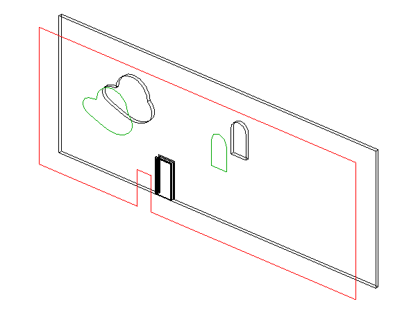
This implementation still does not work for my test wall :-) But at least if I change non-rectangular window family type to a rectangular window it works:
Final Solution
The problem is that my window has top edge is an elliptical curve, and it is located on cylindrical face, so its actual geometry is a bit crazy – Hermite spline interpolated – and this curve does not lie in a plane.
So, the problem is in the creator.CreateModelCurve method.
First of all, let us get to know what curve types are provided in the Revit API:
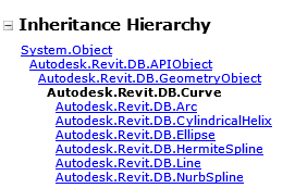
- Line, Arc and Ellipse Curves all lie in a plane, whereas CylindricalHelix, HermitSpline, NurbSpline do not.
- Arc and Ellipse curves have a centre and normal, which define a plane; we can also define a plane that passes a line.
- Other curves should be tessellated, so we need a new method that returns an array of model curves to represent the tessellated curve – that requires numerous lines.
We can easily handle these cases as follows:
- We first test if the curve is a Line; if it is, create a model line from its end points.
- Secondly, we test if the curve is an Arc, then if it is an Ellipse.
- In all other cases, we create multiple lines from the tessellated curve points.
Please refer to CmdWallProfile - final.cs and the updated Creator class using the following code demonstrating the detailed implementation:
  ModelCurve CreateModelCurve(
    Curve curve,
    XYZ origin,
    XYZ normal )
  {
    Plane plane = _creapp.NewPlane( normal, origin );

    SketchPlane sketchPlane = SketchPlane.Create(
      _doc, plane );

    return _credoc.NewModelCurve(
      curve, sketchPlane );
  }

  public ModelCurveArray CreateModelCurves(
    Curve curve )
  {
    var array = new ModelCurveArray();

    var line = curve as Line;
    if( line != null )
    {
      array.Append( CreateModelLine( _doc,
        curve.GetEndPoint( 0 ),
        curve.GetEndPoint( 1 ) ) );

      return array;
    }

    var arc = curve as Arc;
    if( arc != null )
    {
      var origin = arc.Center;
      var normal = arc.Normal;

      array.Append( CreateModelCurve(
        arc, origin, normal ) );

      return array;
    }

    var ellipse = curve as Ellipse;
    if( ellipse != null )
    {
      var origin = ellipse.Center;
      var normal = ellipse.Normal;

      array.Append( CreateModelCurve(
        ellipse, origin, normal ) );

      return array;
    }

    var points = curve.Tessellate();
    var p = points.First();

    foreach( var q in points.Skip( 1 ) )
    {
      array.Append( CreateModelLine( _doc, p, q ) );
      p = q;
    }

    return array;
  }
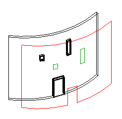
It is done now:
Implemented in the Revit Python Shell
Another interesting aspect of this development to note:
Actually all steps were originally implemented in the Revit Python shell.
The Python code looks pretty and, most important, it is very easy to change it with no need to restart Revit.
For example, the first attempt code looks like this – very short and clear:
  t = Transaction(doc, 'wall elevation profile')
  t.Start()

  colorRed = Color( 255, 0, 0 )
  view = doc.ActiveView
  for wall in selection:
    sideFaceReference = HostObjectUtils.GetSideFaces(
      wall, ShellLayerType.Exterior ) [0]
    face = wall.GetGeometryObjectFromReference(
      sideFaceReference)
    offset = Transform.CreateTranslation(
      5 * wall.Orientation);
    for curveLoop in face.GetEdgesAsCurveLoops():
      curves = doc.Application.Create.NewCurveArray()
      for curve in curveLoop:
        curves.Append(curve.CreateTransformed(offset))

      plane = doc.Application.Create.NewPlane( curves )
      sketchPlane = SketchPlane.Create( doc, plane )

      curveElements = doc.Create.NewModelCurveArray(
        curves, sketchPlane )

      if curveLoop.IsCounterclockwise(wall.Orientation):
        for mcurve in curveElements:
          overrides = view.GetElementOverrides(mcurve.Id)
          overrides.SetProjectionLineColor(colorRed)
          view.SetElementOverrides(mcurve.Id, overrides)

  t.Commit()
Complete External Command
Here is the entire implementation of the new CmdWallProfile Execute3 method, as well as the external command Execute mainline that chooses between the three versions:
  void SetModelCurvesColor(
    ModelCurveArray modelCurves,
    View view,
    Color color )
  {
    foreach( var curve in modelCurves
      .Cast<ModelCurve>() )
    {
      var overrides = view.GetElementOverrides(
        curve.Id );

      overrides.SetProjectionLineColor( color );

      view.SetElementOverrides( curve.Id, overrides );
    }
  }

  /// <summary>
  /// Improved implementation by Alexander Ignatovich
  /// supporting curved wall with curved window,
  /// second attempt, published April 10, 2015:
  /// </summary>
  public Result Execute3(
    ExternalCommandData commandData,
    ref string message,
    ElementSet elements )
  {
    UIApplication uiapp = commandData.Application;
    UIDocument uidoc = uiapp.ActiveUIDocument;
    Application app = uiapp.Application;
    Document doc = uidoc.Document;
    View view = doc.ActiveView;

    Autodesk.Revit.Creation.Application creapp
      = app.Create;

    Autodesk.Revit.Creation.Document credoc
      = doc.Create;

    Reference r = uidoc.Selection.PickObject(
      ObjectType.Element, "Select a wall" );

    Element e = uidoc.Document.GetElement( r );

    Creator creator = new Creator( doc );

    Wall wall = e as Wall;

    if( wall == null )
    {
      return Result.Cancelled;
    }

    using( Transaction tx = new Transaction( doc ) )
    {
      tx.Start( "Wall Profile" );

      // Get the external wall face for the profile
      // a little bit simpler than in the last realization

      Reference sideFaceReference
        = HostObjectUtils.GetSideFaces(
          wall, ShellLayerType.Exterior )
            .First();

      Face face = wall.GetGeometryObjectFromReference(
        sideFaceReference ) as Face;

      // The normal of the wall external face.

      XYZ normal = wall.Orientation;

      // Offset curve copies for visibility.

      Transform offset = Transform.CreateTranslation(
        5 * normal );

      // If the curve loop direction is counter-
      // clockwise, change its color to RED.

      Color colorRed = new Color( 255, 0, 0 );

      // Get edge loops as curve loops.

      IList<CurveLoop> curveLoops
        = face.GetEdgesAsCurveLoops();

      foreach( var curveLoop in curveLoops )
      {
        CurveArray curves = creapp.NewCurveArray();

        foreach( Curve curve in curveLoop )
          curves.Append( curve.CreateTransformed(
            offset ) );

        var isCounterClockwize = curveLoop
          .IsCounterclockwise( normal );

        // Create model lines for an curve loop if it is made

        if( ( (LocationCurve) wall.Location ).Curve
          is Line )
        {
          Plane plane = creapp.NewPlane( curves );

          SketchPlane sketchPlane
            = SketchPlane.Create( doc, plane );

          ModelCurveArray curveElements = credoc
            .NewModelCurveArray( curves, sketchPlane );

          if( isCounterClockwize )
          {
            SetModelCurvesColor( curveElements,
              view, colorRed );
          }
        }
        else
        {
          foreach( var curve in curves.Cast<Curve>() )
          {
            var curveElements = creator.CreateModelCurves( curve );
            if( isCounterClockwize )
            {
              SetModelCurvesColor( curveElements, view, colorRed );
            }
          }
        }
      }
      tx.Commit();
    }
    return Result.Succeeded;
  }

  public Result Execute(
    ExternalCommandData cd,
    ref string msg,
    ElementSet els )
  {
    // Choose which implementation to use.

    int use_execute_nr = 3;

    switch( use_execute_nr )
    {
      case 1: return Execute1( cd, ref msg, els );
      case 2: return Execute2( cd, ref msg, els );
      case 3: return Execute3( cd, ref msg, els );
    }
    return Result.Failed;
  }
CreateModelLine Clean-up
In addition to the CmdWallProfile enhancement, Alexander pointed out that it would help to remove the non-static CreateModelLine(XYZ p, XYZ q) method, since it cannot create even a simple line from (0, 0, 0) to (1, 1, 1), because it tries to draw the line in one of the XOY, XOZ or YOZ planes, which do not contain this slanted line.
So I did :-)
Download
I added Alexander's three versions and the CreateModelLine clean-up to The Building Coder samples and tagged them as the following separate releases:
- release 2015.0.120.3 – before Alexander's CmdWallProfile enhancement
- release 2015.0.120.4 – integrated CmdWallProfile - first attempt.cs
- release 2015.0.120.5 – integrated CmdWallProfile - second attempt.cs
- release 2015.0.120.6 – integrated CmdWallProfile - final.cs
- release 2015.0.120.7 – eliminated and replaced non-static Creator.CreateModelLine taking XYZ start and end point by static overload taking Document as well
For the sake of completeness, here is also ai_CmdWallProfile.zip containing Alexander's original complete sample code and test model.
Many thanks to Alexander for his in-depth research, implementation, support and sharing!