Getting the Wall Elevation Profile
I am back from the vacation in Italy, which I enjoyed very much, especially another visit to the wonderful coast of Amalfi.
To quickly share an interesting new result using the Revit API, here is a solution by Katsuaki Takamizawa to retrieve the wall elevation profile.
It also provides a nice little example of using the ExporterIFCUtils.SortCurveLoops method that we just recently documented.
Says Katsu:
I created some sample code for finding the wall elevation profile and determining its outer and inner loops.
The wall elevation profile topic was already discussed way back in 2008, followed by determination of the related polygon areas.
This sample uses newer methods and the code is much simpler.
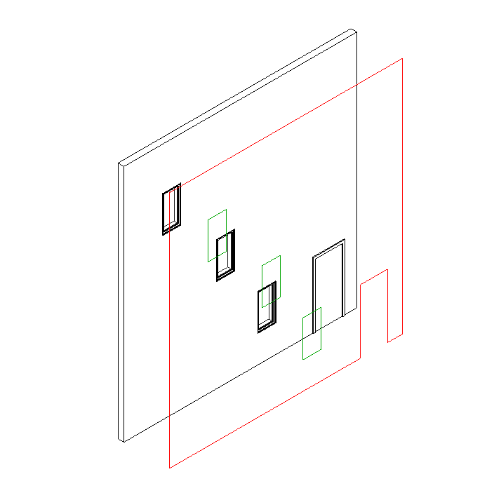
The sample draws model lines based on the existing wall elevation profile.
The outer edge loop is colored in red.
It uses the ExporterIFCUtils.SortCurveLoops method to sort the outer and inner loops.
The outer loop is always counter-clockwise oriented, so we can use the IsCounterclockwise method to detect it.
The result of running the command on a simple wall with a door and two windows looks like this:
Here is the entire implementation of the external command Execute method:
  UIApplication uiapp = commandData.Application;
  UIDocument uidoc = uiapp.ActiveUIDocument;
  Application app = uiapp.Application;
  Document doc = uidoc.Document;
  View view = doc.ActiveView;

  Autodesk.Revit.Creation.Application creapp
    = app.Create;

  Autodesk.Revit.Creation.Document credoc
    = doc.Create;

  Reference r = uidoc.Selection.PickObject(
    ObjectType.Element, "Select a wall" );

  Element e = uidoc.Document.GetElement( r );

  Wall wall = e as Wall;

  using( Transaction tx = new Transaction( doc ) )
  {
    tx.Start( "Wall Profile" );

    // Get the external wall face for the profile

    IList<Reference> sideFaces
      = HostObjectUtils.GetSideFaces( wall,
        ShellLayerType.Exterior );

    Element e2 = doc.GetElement( sideFaces[0] );

    Face face = e2.GetGeometryObjectFromReference(
      sideFaces[0] ) as Face;

    // The normal of the wall external face.

    XYZ normal = face.ComputeNormal( new UV( 0, 0 ) );

    // Offset curve copies for visibility.

    Transform offset = Transform.CreateTranslation(
      5 * normal );

    // If the curve loop direction is counter-
    // clockwise, change its color to RED.

    Color colorRed = new Color( 255, 0, 0 );

    // Get edge loops as curve loops.

    IList<CurveLoop> curveLoops
      = face.GetEdgesAsCurveLoops();

    // ExporterIFCUtils class can also be used for
    // non-IFC purposes. The SortCurveLoops method
    // sorts curve loops (edge loops) so that the
    // outer loops come first.

    IList<IList<CurveLoop>> curveLoopLoop
      = ExporterIFCUtils.SortCurveLoops(
        curveLoops );

    foreach( IList<CurveLoop> curveLoops2
      in curveLoopLoop )
    {
      foreach( CurveLoop curveLoop2 in curveLoops2 )
      {
        // Check if curve loop is counter-clockwise.

        bool isCCW = curveLoop2.IsCounterclockwise(
          normal );

        CurveArray curves = creapp.NewCurveArray();

        foreach( Curve curve in curveLoop2 )
        {
          curves.Append( curve.CreateTransformed( offset ) );
        }

        // Create model lines for an curve loop.

        Plane plane = creapp.NewPlane( curves );

        SketchPlane sketchPlane
          = SketchPlane.Create( doc, plane );

        ModelCurveArray curveElements
          = credoc.NewModelCurveArray( curves,
            sketchPlane );

        if( isCCW )
        {
          foreach( ModelCurve mcurve in curveElements )
          {
            OverrideGraphicSettings overrides
              = view.GetElementOverrides(
                mcurve.Id );

            overrides.SetProjectionLineColor(
              colorRed );

            view.SetElementOverrides(
              mcurve.Id, overrides );
          }
        }
      }
    }
    tx.Commit();
  }
  return Result.Succeeded;
I initially tried to move the model lines using the ElementTransformUtils.MoveElement method to offset them for better visibility.
That did not work.
It seems that these model lines are attached to the wall face, and the MoveElement method cannot move them away from the wall.
So I modified the underlying geometry curves first, before creating model lines from them.
Here is GetWallProfile.zip containing the entire Visual Studio solution, external command source code and add-in manifest.
Many thanks to Katsu-san for implementing and sharing this!