Creating Topography Contours and Building Masses
After diving deep into both Revit MEP and Structure API issues in the past few days, let's round it of with a GIS related topic:
I had an interesting discussion back in the spring of this year with Mohammad Rahmani Asl, Saied Zarrinmehr and Chengde Wu of the Texas A&M University in the Revit API discussion forum on the topic of creating a height dimension for a form.
I finally grabbed some time last weekend to document that discussion thread and publish their interesting application: DataToBim, a Revit add-in that creates topography, building outlines and solid conceptual mass extrusions from text file input data:
Here is the five and a half minute video describing the final completed project:
The initial question from Mohammad was on creating the dimensioning required to extrude the building shape masses.
Later, Saied added background information and motivation on the application itself:
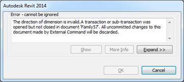
Question: I am creating an application that needs to create dimension for height of a form. I read The Building Coder and the forum posts and used the sample in SDK folder (Window Wizard). I was able to manage everything well but the following error:
The direction of dimension is invalid.
I tried a lot to solve this issue, but I could not find the solution. Two other people had the same problem in the blog but there is no answer for their questions. I would appreciate if you could help me.
Here is saieds_program.zip containing the complete source code and Visual Studio solution together plus some sample data text files.
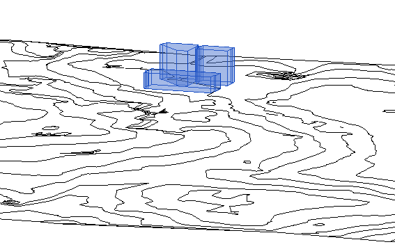
This application imports data from GIS to Revit. When you run it from the add-in manager it creates the topography first and then adds the masses (using extrusion command) on the top of topography:
Please follow these steps:
- Copy the TextForPartialMap folder to your “C:/” drive or copy it to any folder and change paths in the MainClass.Cs for Buildings Road and Contours.
- Open and empty Revit Architecture Project and go to Level 1 View
- Run the application from add in manager
- The program creates the topography using the data in the text files included in the project folder (It takes a few seconds)
- It will ask for a folder to save the mass files (select a folder and click OK)
- Here comes the error:
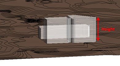
The code attempts to add height dimension to the mass and label it with the height parameter (please see the DataToBuilding.cs then CreateFamilyFile Function when we try to create the dimension).
The error that we receive is highlighted with a few stars in comment in the code.
Answer: I had some trouble rebuilding your project.
I first tried to use the current version of the clipper library, clipper_ver6.1.3a.zip.
That no longer defines the AddPolygons method, but AddPaths instead.
I then reverted back to a version I had used previously, clipper_ver5.1.6.zip.
That does not yet define the StrictlySimple property.
After commenting out that in your code I was able to compile.
I tried running it, and encountered the error System.ArgumentException: "Could not find the path!"
That was due to your implementation of the familyTemplateAddress method, which only provides support for the imperial library.
I only have the metric library installed, so I added support for that.
I was able to reproduce the error that you run into, saying 'The direction of dimension is invalid. A transaction or sub-transaction was opened but not closed in document 'Family2'. All uncommitted changes to this document made by External Command will be discarded.'
Looking at the name of the view, I see 'RayTracer View', created by the CreateIsometric method your method createView3d.
Try adding a dimension to that view in the user interface and see what happens :-)
As far as I know, adding dimensioning requires a 2D view, and the dimensioning must lie in the view plane.
I would therefore suggest that you search for or create a suitable such view, presumably an elevation view, and use that to create the dimensioning.
Some samples are available on the net, e.g. by searching for Revit API NewDimension.
Response I appreciate your attention and the time that you spent on the issue that Mohammad reported. Although I have never contacted you but I have read every single post of your blog. I owe you a lot. Let me know when you come over College Station, Texas to take you out to a restaurant :-)
Since you have spent quite a bit of time reading and trying to understand our code you might be curious to have an overview of the application. I am the main developer of an application in Revit that reads ArcGIS shape files and automatically creates a BIM model that contains GIS tabular information in the form of Revit parameters. Developing this application is only possible in Revit 2014 in which the API library includes constructors for SiteSubRegion and BuildingPadType. This application is part of a research project in which the user interface also conducts queries in Revit to search, find and visualize building masses based on their parameter values. The UI also automates the creation of facades on the faces of a mass. The project is at its final steps.
My colleague, Mohammad, was working to connect the parameters to control the geometry of the mass. Since Mohammad and I were working on the same class "DataToBuilding.cs" we made some mistakes. The "ray tracer" view was created on the main project document to find the elevation of the building (which is not usually available in GIS). In this view rays will be shot vertically from the corners of the building footprint; the closet distances will be measured, and the average distances will be calculated to find the elevation of the building on the topography. Then we will create a new mass family and locate it on the topography. Here is where we used the address of the template family using imperial folder. We will create the new "Conceptual Mass" families in Revit API and that is where the issues are raised.
It is easy to create a new family document and create new extrusions using Revit API library. The corners of building footprints that are retrieved from GIS data are set according to the North American datum and the numbers might be big double values. As a result when you create a new extrusion in a mass family that is generated with API, the extrusion is very likely be placed far from the default visible range of the default view of a family. You can nonetheless load these families in the project and see their preview on the project browser when you want to place an instance of these families! Creating new dimensions also has the same view issue. A family document that is created by API does not have active view and manipulating the view properties to expand the range of visibility seems to be impossible maybe because there is not any view at all. I could solve the problem of family visibility by translating the building footprint to the canter of the family datum, creating the extrusion, saving the family, loading the family into the project file and finally translating the family back in its original location. This strategy worked to solve the problem of viewing the geometry of the family; however, it cannot be applied to take care of the dimension issue. Like many other geometric elements, dimensions in Revit are also view-dependent.
I can summarize our problem in this way, "how could we create a 2D elevation view in a family that was generated by Revit API?"
Thanks again for your attention. I would be happy to provide more detailed explanation of the application for your blog when the development is completed.
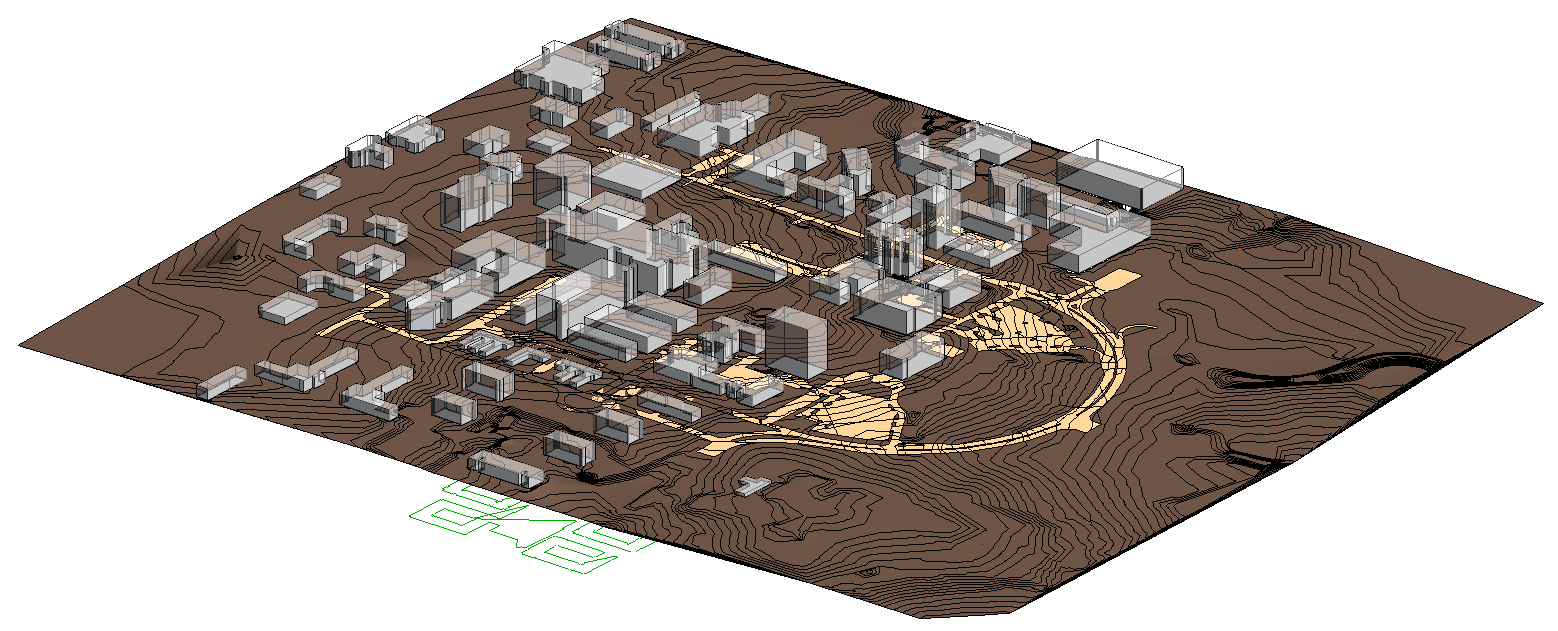
PS: In the previous model you can activate the visibility of masses to see the buildings. Our results will look like this image showing part of the Texas A&M main campus:
The clipper library was used to perform polygon Boolean operations. We also worked with a couple of other external libraries but when simplifying the application to send it to you we forgot to remove the clipper library.
Later: To address the problem at hand, I now found The Building Coder discussion on section view creation.
The Revit 2014 API doc.Create.NewViewSection method is now replaced by a static member of ViewSection class. I guess viewSection is what we need to use. Is that true?
Later still: The problem is solved. A new family document has a list of views that can be retrieved using a FilteredElementCollector and filtered to find views of type elevation, ViewType.Elevation. We even did not need to generate any new views.
Answer: I am very glad to hear that you solved it.
The approach searching for an existing elevation view and adding the dimensioning to that sounds perfect, as long as you do not care specifically which view it is added to.
Yes, you would use the static ViewSection.CreateSection method nowadays instead of NewViewSection. Here are some samples of using that:
- Change Section View Type and Hide Cut Line
- Create Section View Parallel to Wall
- Set View Section Box to Match Scope Box
- Language Independent Section View Type Id Retrieval
I later put together dedicated topic lists on creating dimensioning and creating and setting up section views.
Response: Here is the updated and somewhat polished Visual Studio solution.
Unfortunately, I cannot release more from the on-going research that is not published yet.
I added the text files (data from GIS) to the resources of the VS project so that people do not get into the trouble of setting the folder names.
I also would like to add something about the method we used to create the TopographicSurface. The static method to create an instance of TopographicSurface class asks for a list of XYZ points to create a mesh representing the topography in Revit. Unlike Revit, ArcGIS represents topography with contour curves. The contours in GIS can intersect with each other or be drawn on the top of each other, meaning that we may get points with identical X and Y values. The create method in TopographicSurface class will throw and exception when the list of points includes points with identical X and Y values. I followed two solutions to remove identical points: the geometric solution and the non-geometric solution.
In the geometric solution I recursively created rectangular subareas and in each subareas checked each pair of points to check if they have identical x and y values. This solution took days to implement and took hours to work on small topographic surface. I decided to use the non-geometric solution taking advantage of the internal structure of a dictionary. In my dictionary each key-value pair includes a key that is uniquely defined based on the X and Y of each XYZ point and the point itself as the value. When adding new key-values to the dictionary, if the keys are the same, meaning that the points are on the top of each other, the dictionary will throw an exception. To create an appropriate key I converted the X and Y values of each point to strings and concatenated the string values to create one unique string. This method worked elegantly – fast and accurate.
Answer: I compiled and tested the original code on Revit 2014, publishing it in the DataToBimCountoursAndBuildings GitHub repository as release 2014.0.0.0.
I migrated it to Revit 2015 and created release 2015.0.0.0 as a snapshot of that.
Finally, I cleaned it up a bit further, mainly by encapsulating all transactions in 'using' statements, because using using automagically disposes and rolls back, to create the current release 2015.0.0.1.
Don't forget to turn on visibility for Mass and Topography in the View > Visibility/Graphics overrides when testing.
Many thanks to Saied, Mohammad and Chengde for all their work and research on this!