Creating a Sloped Wall
Several questions concerning programmatic creation of sloped walls came up recently, so let's take a look at that, point to some existing samples, and implement a fantastic new one that does it all, including mass family creation, instance insertion and face creation in one fell swoop:
- How to programmatically create a sloped wall
- Sloped wall versus sloped slab
- Creating a sloped wall from mass
- The Creator CreateModelLine method
- The Building Coder Samples download
- Floor creation fails for foundation floor types
Before getting to that, I'll just mention my outing last weekend.
Last weekend saw splendid weather in all of Switzerland, for a change.
I grabbed the chance to go on a tour with my friend Nik.
We walked up from the Kandersteg train station to the Blümlisalphütte mountain lodge at 2834 m in the dark, arriving at midnight.
Next day, we climbed the Wildi Frau, 3274 m, via its south ridge, finding our own route, because we stupidly missed the normal ascent starting point at the north end of the west wall. It is an easy climb, and was exciting and novel for Nik, being his first alpine one ever:

How to Programmatically Create a Sloped Wall
In the user interface, a sloped wall must be hosted on face of a mass and assigned the wall category.
This functionality was made available programmatically by the Revit 2011 API:
Create sloped wall on mass face
The method
- FaceWall.Create()
creates a new instance of a face wall on the sloped face of a mass.
We discussed it twice already, looking at the FaceWall class, slanted walls and creating a FaceWall on a slanted mass face.
It was probably a mistake to use the word 'slanted' instead of 'sloped', I'm afraid.
So now we get to revisit the question again:
Sloped Wall versus Sloped Slab
Question: The wall creation method in the Revit API does not take in a slope:
  Wall.Create( revitDoc, curves, wallType.Id,
    level.Id, isStructural );
However, you can create a sloped floor slab:
  doc.Create.NewSlab( profile, level, slopedArrow,
    slope, isStructural );
We often model structures with walls that are not quite vertical, and when transferring these to Revit they become floors, which I would like to avoid.
Is there a way to create sloped walls through the Revit API?
Answer: The usual Revit way for making non-vertical walls is to take the face of a mass and create the wall on its face.
In the API this involves creating a mass family that has the face at the target slope, placing the mass instance in the project, and then creating the wall with FaceWall.Create.
For more details, take a look at the sample below.
Creating a Sloped Wall from Mass
Here is an interesting discussion on creating a slanted wall from a mass element raising and expanding a number of important Revit API aspects, some of which we have touched on in the past, such as
- The FaceWall class and slanted walls
- Creating and inserting a mass family to replace an in-place mass
- Need for intermediate regeneration
- Optimising filtering
- Iteration order
The answer was originally written by Adam Nagy way back in the Revit 2012 timeframe, and the code in the query is also that old.
I updated the code in the answer, though, and integrated it into The Building Coder samples, in a new command CmdFaceWall.
Question: I'd like to create sloped walls through the API. In the user interface, this can be achieved by creating a mass object and then selecting its face for the wall.
It seem impossible to create an in-place mass element through the API, so I'm creating a mass family programmatically and then inserting an instance of it in the project instead. For some reason, however, its geometry always returns null.
Here is the code (copy and paste to an editor to see the truncated lines in full):
  public static void SlopedWallTest(
    ExternalCommandData revit )
  {
    Document massDoc = revit.Application.Application.NewFamilyDocument(
        @"C:\ProgramData\Autodesk\RAC 2012\Family Templates\English_I\Conceptual Mass\Mass.rft" );

    Transaction transaction = new Transaction( massDoc );
    transaction.SetName( "TEST" );
    transaction.Start();

    ExternalCommandData cdata = revit;
    Autodesk.Revit.ApplicationServices.Application app = revit.Application.Application;
    app = revit.Application.Application;

    // Create one profile
    ReferenceArray ref_ar = new ReferenceArray();

    Autodesk.Revit.DB.XYZ ptA = new XYZ( 0, 0, 0 );
    XYZ ptB = new XYZ( 0, 30, 0 );
    ModelCurve modelcurve = MakeLine( revit.Application, ptA, ptB, massDoc );
    ref_ar.Append( modelcurve.GeometryCurve.Reference );

    ptA = new XYZ( 0, 30, 0 );
    ptB = new XYZ( 2, 30, 0 );
    modelcurve = MakeLine( revit.Application, ptA, ptB, massDoc );
    ref_ar.Append( modelcurve.GeometryCurve.Reference );

    ptA = new XYZ( 2, 30, 0 );
    ptB = new XYZ( 2, 0, 0 );
    modelcurve = MakeLine( revit.Application, ptA, ptB, massDoc );
    ref_ar.Append( modelcurve.GeometryCurve.Reference );

    ptA = new XYZ( 2, 0, 0 );
    ptB = new XYZ( 0, 0, 0 );
    modelcurve = MakeLine( revit.Application, ptA, ptB, massDoc );
    ref_ar.Append( modelcurve.GeometryCurve.Reference );

    // The extrusion form direction
    XYZ direction = new XYZ( -6, 0, 50 );
    Form form = massDoc.FamilyCreate.NewExtrusionForm( true, ref_ar, direction );
    transaction.Commit();

    if( File.Exists( @"C:\TestFamily.rfa" ) )
      File.Delete( @"C:\TestFamily.rfa" );

    massDoc.SaveAs( @"C:\TestFamily.rfa" );

    if( !revit.Application.ActiveUIDocument.Document.LoadFamily( @"C:\TestFamily.rfa" ) )
      throw new Exception( "DID NOT LOAD FAMILY" );

    Family family = null;
    foreach( Element el in new FilteredElementCollector(
        revit.Application.ActiveUIDocument.Document ).WhereElementIsNotElementType().ToElements() )
    {
      if( el is Family )
      {
        if( ( (Family) el ).Name.ToUpper().Trim().StartsWith( "TEST" ) )
          family = (Family) el;
      }
    }

    FamilySymbol fs = null;
    foreach( FamilySymbol sym in family.Symbols )
      fs = sym;

    // Create a family instance.
    revit.Application.ActiveUIDocument.Document.Create.NewFamilyInstance(
        new XYZ( 0, 0, 0 ), fs, revit.Application.ActiveUIDocument.Document.ActiveView.Level,
        StructuralType.NonStructural );

    WallType wallType = null;
    foreach( WallType wt in revit.Application.ActiveUIDocument.Document.WallTypes )
    {
      if( FaceWall.IsWallTypeValidForFaceWall( revit.Application.ActiveUIDocument.Document, wt.Id ) )
      {
        wallType = wt;
        break;
      }
    }

    foreach( Element el in new FilteredElementCollector(
        revit.Application.ActiveUIDocument.Document ).WhereElementIsNotElementType().ToElements() )
    {
      if( el is FamilyInstance )
      {
        if( ( (FamilyInstance) el ).Symbol.Family.Name.ToUpper().StartsWith( "TEST" ) )
        {
          Options options = revit.Application.Application.Create.NewGeometryOptions();
          options.ComputeReferences = true;
          options.View = revit.Application.ActiveUIDocument.Document.ActiveView;
          GeometryElement geoel = el.get_Geometry( options );

          // Attempt to create a slopped wall from the geometry.
          for( int i = 0; i < geoel.Objects.Size; i++ )
          {
            if( geoel.Objects.get_Item( i ) is Solid )
            {
              Solid solid = (Solid) geoel.Objects.get_Item( i );
              for( int j = 0; j < solid.Faces.Size; j++ )
              {
                try
                {
                  if( solid.Faces.get_Item( i ).Reference != null )
                  {
                    FaceWall.Create( revit.Application.ActiveUIDocument.Document,
                        wallType.Id, WallLocationLine.CoreCenterline,
                        solid.Faces.get_Item( i ).Reference );
                  }
                }
                catch( System.Exception e )
                {
                  System.Windows.Forms.MessageBox.Show( e.Message );
                }
              }
            }
          }
        }
      }
    }
  }

  public static ModelCurve MakeLine( UIApplication app, XYZ ptA, XYZ ptB, Document doc )
  {
    // Create plane by the points
    Line line = app.Application.Create.NewLine( ptA, ptB, true );
    XYZ norm = ptA.CrossProduct( ptB );
    if( norm.GetLength() == 0 ) norm = XYZ.BasisZ;
    Plane plane = app.Application.Create.NewPlane( norm, ptB );
    SketchPlane skplane = doc.FamilyCreate.NewSketchPlane( plane );
    // Create line here
    ModelCurve modelcurve = doc.FamilyCreate.NewModelCurve( line, skplane );
    return modelcurve;
  }
Answer: You always need to call the Document.Regenerate method if you wish to use information from the database that was created as a result of the changes you made inside the transaction.
If not, you will be accessing so-called 'stale' information.
The Building Coder defines a whole topic list on the need to regenerate.
Once I added that call to the code after inserting the mass instance, the desired geometry was returned.
I also modified the filtering part of your code to make it more effective.
The more you narrow down the selection using the Revit API, the faster your code will be.
Another problem with your code is in the iteration part.
Many objects give back a new instance each time you call them.
In the case of collections, the objects inside these instances might be in a different order each time.
For instance, instead of making an iteration loop and keep calling solid.Faces.get_Item(i), which will return a new different collection of the solids faces on each call, you should make one single call to and save a reference to the result of the solid.Faces collection and then iterate through that.
A nice way to achieve this is by simply using a foreach statement on it.
Also, instead of passing in ActiveView.Level as the owner for the mass instance you should pass in ActiveView.GenLevel.
If the mass has no owner, the API is not able to create a FaceWall on the mass face.
In fact, if you try it using ActiveView.Level, the call to FaceWall.Create will throw an exception saying, "Could not create a face wall."
Here is the code updated accordingly and migrated to Revit 2015:
  const string _conceptual_mass_template_path
    = "C:/ProgramData/Autodesk/RVT 2015"
    + "/Family Templates/English/Conceptual Mass"
    + "/Metric Mass.rft";

  const string _family_name = "TestFamily";

  const string _family_path = "C:/" + _family_name + ".rfa";

  static ModelCurve MakeLine(
    Document doc,
    XYZ p,
    XYZ q )
  {
    // Create plane by the points

    Line line = Line.CreateBound( p, q );
    XYZ norm = p.CrossProduct( q );
    if( norm.GetLength() == 0 ) { norm = XYZ.BasisZ; }
    Plane plane = new Plane( norm, q );

    SketchPlane skplane = SketchPlane.Create(
      doc, plane );

    // Create line

    return doc.FamilyCreate.NewModelCurve(
      line, skplane );
  }

  /// <summary>
  /// Create an extrusion form in the given
  /// conceptual mass family document.
  /// </summary>
  static void CreateMassExtrusion(
    Document doc )
  {
    using( Transaction tx = new Transaction( doc ) )
    {
      tx.Start( "Create Mass" );

      // Create profile

      ReferenceArray refar = new ReferenceArray();

      XYZ[] pts = new XYZ[] {
        new XYZ( -10, -10, 0 ),
        new XYZ( +10, -10, 0 ),
        new XYZ( +10, +10, 0 ),
        new XYZ( -10, +10, 0 ) };

      int j, n = pts.Length;

      for( int i = 0; i < n; ++i )
      {
        j = i + 1;

        if( j >= n ) { j = 0; }

        // The Creator.CreateModelLine method creates
        // pretty arbitrary sketch planes, which causes
        // the NewExtrusionForm method to fail, saying
        // "Cannot create extrude form."

        //ModelCurve c = Creator.CreateModelLine( doc, pts[i], pts[j] );

        ModelCurve c = MakeLine( doc, pts[i], pts[j] );

        refar.Append( c.GeometryCurve.Reference );
      }

      //doc.Regenerate();

      // The extrusion form direction and length.
      // The direction must be perpendicular to the
      // plane determined by profile. The length
      // must be non-zero.

      XYZ direction = new XYZ( /*-6*/ 0, 0, 20 );

      Form form = doc.FamilyCreate.NewExtrusionForm( // Cannot create extrude form.
        true, refar, direction );

      tx.Commit();
    }
  }

  static void CreateFaceWalls(
    Document doc )
  {
    Application app = doc.Application;

    Document massDoc = app.NewFamilyDocument(
      _conceptual_mass_template_path );

    CreateMassExtrusion( massDoc );

    //if( File.Exists( _family_path ) )
    //  File.Delete( _family_path );

    SaveAsOptions opt = new SaveAsOptions();
    opt.OverwriteExistingFile = true;

    massDoc.SaveAs( _family_path, opt );

    using( Transaction tx = new Transaction( doc ) )
    {
      tx.Start( "Create FaceWall" );

      if( !doc.LoadFamily( _family_path ) )
        throw new Exception( "DID NOT LOAD FAMILY" );

      Family family = new FilteredElementCollector( doc )
        .OfClass( typeof( Family ) )
        .Where<Element>( x => x.Name.Equals( _family_name ) )
        .Cast<Family>()
        .FirstOrDefault();

      FamilySymbol fs = doc.GetElement(
        family.GetFamilySymbolIds().First<ElementId>() )
          as FamilySymbol;

      // Create a family instance

      Level level = doc.ActiveView.GenLevel;

      FamilyInstance fi = doc.Create.NewFamilyInstance(
        XYZ.Zero, fs, level, StructuralType.NonStructural );

      doc.Regenerate(); // required to generate the geometry!

      // Determine wall type.

      WallType wallType = new FilteredElementCollector( doc )
        .OfClass( typeof( WallType ) )
        .Cast<WallType>()
        .Where<WallType>( x => FaceWall.IsWallTypeValidForFaceWall( doc, x.Id ) )
        .FirstOrDefault();

      // Retrieve mass element geometry.

      Options options = app.Create.NewGeometryOptions();
      options.ComputeReferences = true;

      //options.View = doc.ActiveView; // conceptual mass is not visible in default view

      GeometryElement geo = fi.get_Geometry( options );

      // Create a sloped wall from the geometry.

      foreach( GeometryObject obj in geo )
      {
        Solid solid = obj as Solid;

        if( null != solid )
        {
          foreach( Face f in solid.Faces )
          {
            Debug.Assert( null != f.Reference,
              "we asked for references, didn't we?" );

            PlanarFace pf = f as PlanarFace;

            if( null != pf )
            {
              XYZ v = pf.Normal;

              // Errors:
              //
              // Could not create a face wall.
              //
              // Caused by using ActiveView.Level
              // instead of ActiveView.GenLevel.
              //
              // This reference cannot be applied to a face wall.
              //
              // Caused by using this on a horizontal face.

              if( !Util.IsVertical( v ) )
              {
                FaceWall.Create(
                  doc, wallType.Id,
                  WallLocationLine.CoreCenterline,
                  f.Reference );
              }
            }
          }
        }
      }
      tx.Commit();
    }
  }
Many thanks to Adam for this insightful solution!
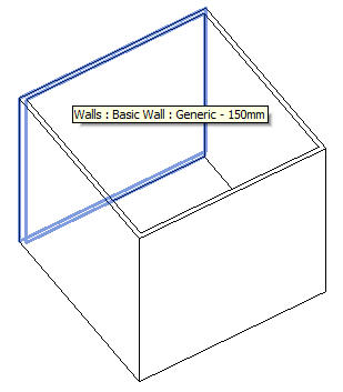
Note that I discovered another situation that can cause the FaceWall.Create method to fail saying, "This reference cannot be applied to a face wall", namely a horizontal face.
After eliminating the two horizontal faces on the cube that I defined, the resulting four face walls finally look like this:
The Creator CreateModelLine Method
I struggled with several issues getting this to run in Revit 2015 and in The Building Coder sample add-in.
One really hard problem that I created for myself was caused by switching away from the MakeLine method shown above.
It was originally defined in one of the Revit SDK NewForm massing samples, in the module SDK/Samples/Massing/NewForm/CS/Command.cs.
Since the Creator class in The Building Coder samples already defines a similar method, CreateModelLine, I decided to use that instead.
This required a modification to work in a family document – it was previously only usable in the project environment.
The new version looks like this:
  /// <summary>
  /// Create a model line between the two given points.
  /// Internally, it creates an arbitrary sketch
  /// plane given the model line end points.
  /// </summary>
  public static ModelLine CreateModelLine(
    Document doc,
    XYZ p,
    XYZ q )
  {
    if( p.DistanceTo( q ) < Util.MinLineLength ) return null;

    // Create sketch plane; for non-vertical lines,
    // use Z-axis to span the plane, otherwise Y-axis:

    XYZ v = q - p;

    double dxy = Math.Abs( v.X ) + Math.Abs( v.Y );

    XYZ w = ( dxy > Util.TolPointOnPlane )
      ? XYZ.BasisZ
      : XYZ.BasisY;

    XYZ norm = v.CrossProduct( w ).Normalize();

    Plane plane = new Plane( norm, p );

    SketchPlane sketchPlane = SketchPlane.Create( doc, plane );

    Line line = Line.CreateBound( p, q );

    ModelCurve curve = doc.IsFamilyDocument
      ? doc.FamilyCreate.NewModelCurve( line, sketchPlane )
      : doc.Create.NewModelCurve( line, sketchPlane );

    return curve as ModelLine;
  }
It now checks whether the document is a family and uses either doc.Create or doc.FamilyCreate, as appropriate.
So far, so good.
However, try as I might, the extrusion creation call to NewExtrusionForm always failed saying, "Cannot create extrude form."
I debugged myself stupid, tested that code in the Massing NewForm SDK sample achieved its goal, and tediously eliminated all the differences between that implementation and mine until I finally found the reason.
I finally figured out that the arbitrary sketch planes generated by the CreateModelLine method were causing this.
Each of the model lines I used to define the extrusion profile was located on a different sketch plane with wildly different normal vectors.
The MakeLine method is more reliable, and replacing the former by the latter finally solved the problem.
The Building Coder Samples Download
You can download the most up-to-date version from The Building Coder samples GitHub repository.
The version discussed above is 2015.0.113.1.
Floor Creation Fails for Foundation Floor Types
After all this talk about walls and the requirement that they not be horizontal, let's mention another rather cryptic and misleading error message that can come up when creating a floor:
Question: I am using the Document.NewFloor method to create a floor.
However, it is displaying an error message saying, "Could not construct a proper face with the input curves to create a floor correctly".
Answer: After further debugging, I found that the cause of the error is not the face or curves, but the floor type I am trying to use.
The floor creation does not accept a FloorType with IsFoundationSlab == true.
If I provide a FloorType with IsFoundationSlab == false, then the floor is created successfully.
I would assume that the foundation slab types have to be used with the Document.NewFoundationSlab method, and that there are fundamental differences in behaviour between floor and foundation types.
If possible, it would be nice to update the exception to explain that the FloorType is invalid, not the curves.
Addendum: Some obvious possible differences might be functionality such as support for a slanted slabs and multiple layers in the compound structure.
When you run into a geometrical error message such as the one mentioned above, you can often obtain more detailed error messages and information on the causes by creating intermediate model lines and then trying to make use of those appropriately via the user interface, as described for debugging form creation.