Profiling Revit Add-ins and RoomEditorApp Enhancements
Today we take a look a profiling tool that works with Revit add-ins, and a few small new enhancements to my RoomEditorApp.
The entire following article was contributed by Ben Bishoff of Ideate Software:
Profiling Revit Add-ins using GlowCode
Performance profiling tools allow you to increase the speed of your code by pinpointing slow methods and methods that are called excessively. For the past several releases, we have successfully used GlowCode real-time performance profiler (www.glowcode.com) to analyse and improve the speed of our Revit add-ins.
Unfortunately, since at least Revit 2011, we have been unable to profile our add-ins using standard .NET profiling tools like ANTS Performance Profiler. I suspect this is caused by the way the managed .NET Revit API is connected to the underlying native Revit code base.
GlowCode is unique among profiling tools in that it can profile both managed (.NET) and native (C++) applications. It appears that the ability to work in a mixed code environment allows GlowCode to drill through and profile the managed add-in code hosted inside the native Revit application.
After setting up a GlowCode project (see below), you launch Revit through GlowCode and run your add-in. Among other statistics, GlowCode will record the time spent within each code method and the number of times each code method was visited. From there, there are many ways to 'slice and dice' the information GlowCode records. In general, you are presented with tree views you can use to drill-down and find slow methods.

And here is where the detective work (and fun) begins! It is always eye opening to actually see where your code spends its time. Two of the biggest gotchas we have encountered in our code have been repetitive API calls, and reading and writing large collections of data.
Using profiling, we have identified places in our code where we make repetitive calls to the same Revit API method to get the same static information. In this case, it makes sense to cache the data in a collection and later retrieve the data from that collection instead of through a Revit API call. Using the proper data structure to the store data, however, is crucial.
If you never learned the concepts of Big O notation, or it has been a while since Computer Science 101, now is the time to refresh your knowledge. Googling 'Big O notation' will return many good basic tutorials, but here is the core idea: the time it takes to read and write data to a collection of data greatly depends on the type of data structure you use. An array or list data structure, while easy to create, is slow to search. In general, the time it takes to search a list depends directly on the size of the list. In contrast, a hash data structure (or its variant the dictionary), while more complex to set up, is much faster to read. If done right and you have defined an appropriate hash method for the data you are storing, retrieving data from a hash can approach near constant time. In other words, searching for data in a hash of 10 objects takes almost the same amount of time as in a hash storing thousands of objects. In short, learn to love hashes.
GlowCode has a 21-day free trial, standalone license are $499 USD. We have found it well worth the investment - if you don't profile your code you're flying blind. Case in point, using profiling we have found commands that slowed down by a factor of 10x or more due to innocent changes made during a release. Profiling quickly identified these bottlenecks, and many times changing just a few lines of code remedied the problem.
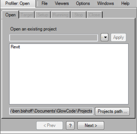
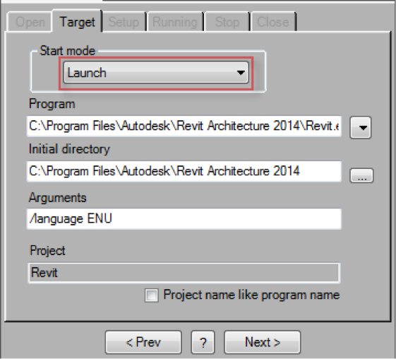
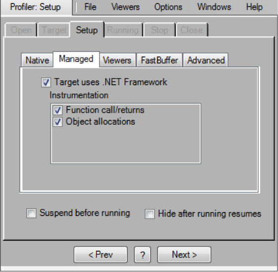
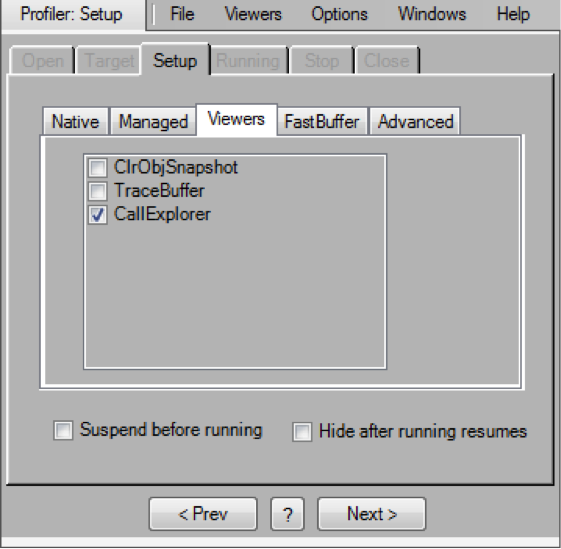
What follows are screenshots of the GlowCode project settings I have used to successfully profile our Revit add-ins. For detailed set up see GlowCode Help see topic:
- How To > Profile Performance > (Native & Managed) > Tutorial: Quickstart profiling instructions

Note that the profiler must launch Revit, cf. Target tab > Start mode > Launch. Unlike debugging in Microsoft Visual Studio, the .NET framework does not support profiling applications by attaching to applications that are already running.

Managed setup options:

Viewer setup:

Thank you very much for this fine and important article, Ben!
I hope it encourages others to profile and optimise their add-ins as well.
RoomEditorApp Inches Forward
The Tech Summit in June is nearing inexorably.
The last date to submit my presentation is end of next week, which is getting closer even faster.
I barely started development yet.
My goals:
- Display sheet, views and floor plan geometry
- Store, edit and update non-graphical property data
- Improve the 2D graphical editing
After a ten-day pause in development, I picked it up again and posted two new releases yesterday to the RoomEditorApp GitHub repository:
Multi-Category Filter
One of the steps I discussed in the previous instalments was the interactive
selection of categories to
export, returning a list of category objects, i.e. List<Category> categories.
I initially thought of converting the list to a dictionary for faster lookup when filtering for elements to export.
A dictionary can be generated from a list by calling the ToDictionary method like this:
  // Convert category list to a dictionary for
  // more effective repeated lookup.

  Dictionary<ElementId, Category> catLookup =
    categories.ToDictionary<Category, ElementId>(
      c => c.Id );
However, no post processing will ever be as fast as supplying an element filter to the Revit filtered element collector.
So how can I effectively convert a list of categories to an appropriate element filter?
Well, easily, in one single line of code, albeit rather lengthy when unravelled:
  // No, much better: set up a reusable element
  // filter for the categories of interest:

  ElementFilter categoryFilter
    = new LogicalOrFilter( categories
      .Select<Category, ElementCategoryFilter>(
        c => new ElementCategoryFilter( c.Id ) )
      .ToList<ElementFilter>() );
What does this line of code do?
For each category, it creates a corresponding category filter.
All of these filters are collected into a list used to initialise a Boolean OR of them all.
In the end, any element that matches one of the listed categories will pass the filter.
All of the filters involved are quick filters.
UploadSheet Method Outline
I started implementing the UploadSheet method to upload a sheet, the views it contains, and all the elements displayed in them, ignoring elements not belonging to one of the selected categories.
What it does in this state is traverse the given structures and access the relevant geometry.
It shows how the category filter is applied to retrieve the view specific geometry for the elements of interest, and how the family instance location transformation and element geometry can be handled.
The logic to create a dictionary of the symbol geometry and only process each symbol once is in place.
  /// <summary>
  /// Upload given sheet and the views it contains
  /// to the cloud repository, ignoring all elements
  /// not belonging to one of the selected categories.
  /// </summary>
  static void UploadSheet(
    ViewSheet sheet,
    ElementFilter categoryFilter )
  {
    bool list_ignored_elements = false;

    Document doc = sheet.Document;

    Options opt = new Options();

    // Map symbol UniqueId to symbol geometry

    Dictionary<string, JtLoop> symbolGeometry
      = new Dictionary<string, JtLoop>();

    // List of instances referring to symbols

    List<JtPlacement2dInt> familyInstances
      = new List<JtPlacement2dInt>();

    // There is no need and no possibility to set
    // the detail level when retrieving view geometry.
    // An attempt to specify the detail level will
    // cause writing the opt.View property to throw
    // "DetailLevel is already set. When DetailLevel
    // is set view-specific geometry can't be
    // extracted."
    //
    //opt.DetailLevel = ViewDetailLevel.Coarse;

    Debug.Print( sheet.Name );

    foreach( ViewPlan v in sheet.Views
      .OfType<ViewPlan>()
      .Where<ViewPlan>( v => IsFloorPlan( v ) ) )
    {
      Debug.Print( "  " + v.Name );

      opt.View = v;

      FilteredElementCollector els
        = new FilteredElementCollector( doc, v.Id )
          .WherePasses( categoryFilter );

      foreach( Element e in els )
      {
        //Debug.Print( "  " + e.Name );

        GeometryElement geo = e.get_Geometry( opt );

        // Call GetTransformed on family instance geo.
        // This converts it from GeometryInstance to ?

        FamilyInstance f = e as FamilyInstance;

        if( null != f )
        {
          Location loc = e.Location;

          // Simply ignore family instances that
          // have no valid location, e.g. panel.

          if( null == loc )
          {
            if( list_ignored_elements )
            {
              Debug.Print( "    ... ignored "
                + e.Name );
            }
            continue;
          }

          familyInstances.Add(
            new JtPlacement2dInt( f ) );

          FamilySymbol s = f.Symbol;

          string uid = s.UniqueId;

          if( symbolGeometry.ContainsKey( uid ) )
          {
            if( list_ignored_elements )
            {
              Debug.Print( "    ... already handled "
                + e.Name + " --> " + s.Name );
            }
            continue;
          }

          // Replace this later to add real geometry.

          symbolGeometry.Add( uid, null );

          // Retrieve family instance geometry
          // transformed back to symbol definition
          // coordinate space by inverting the
          // family instance placement transformation

          LocationPoint lp = e.Location
            as LocationPoint;

          Transform t = Transform.CreateTranslation(
            -lp.Point );

          Transform r = Transform.CreateRotationAtPoint(
            XYZ.BasisZ, -lp.Rotation, lp.Point );

          geo = geo.GetTransformed( t * r );
        }

        Debug.Print( "    " + e.Name );

        foreach( GeometryObject obj in geo )
        {
          // This was true before calling GetTransformed.
          //Debug.Assert( obj is Solid || obj is GeometryInstance, "expected only solids and instances" );

          // This was true before calling GetTransformed.
          //Debug.Assert( ( obj is GeometryInstance ) == ( e is FamilyInstance ), "expected all family instances to have geometry instance" );

          Debug.Assert( obj is Solid || obj is Line, "expected only solids and lines after calling GetTransformed on instances" );

          Debug.Assert( Visibility.Visible == obj.Visibility, "expected only visible geometry objects" );

          Debug.Assert( obj.IsElementGeometry, "expected only element geometry" );
          //bool isElementGeometry = obj.IsElementGeometry;

          // Do we need the graphics style?
          // It might give us horrible things like
          // colours etc.

          ElementId id = obj.GraphicsStyleId;

          //Debug.Print( "      " + obj.GetType().Name );

          Solid solid = obj as Solid;

          if( null == solid )
          {
            Debug.Print( "      " + obj.GetType().Name );
          }
          else
          {
            int n = solid.Edges.Size;

            if( 0 < n )
            {
              Debug.Print(
                "      solid with {0} edges", n );

              foreach( Edge edge in solid.Edges )
              {
                Curve c = edge.AsCurve();

                Debug.Print( "        "
                  + edge.GetType().Name + ": "
                  + c.GetType().Name );
              }
            }
          }
        }
      }
    }
  }
Here is an excerpt of the output it generates for a sheet containing two views, one of them displaying a wall of type 'Cav - 102 75i 100 p - Lwt', a desk and a chair, among many other things:
Sheet view of Level 0 and 1
  Level 0
    Cav - 102 75i 100 p - Lwt
      solid with 12 edges
        Edge: Line
        ...
        Edge: Line
    1525 x 762mm
      Line
      Line
      Line
      Line
    Office Chair
      solid with 12 edges
        Edge: Line
        ...
        Edge: Line
      solid with 4 edges
        Edge: Line
        Edge: Line
        Edge: Line
        Edge: Line
Lots more processing to do here before I have this displaying properly in SVG in the browser, plus I need to work out all the proper scalings and transformations from Revit model space to the view, the size and location of the views on the sheet, and the sheet placement in the browser SVG canvas.
Split Point2dIntLoop.cs Module
The SVG generation is implemented in the JtLoop and JtLoops classes, which were defined in a C# module named Point2dIntLoop.cs.
To simplify navigation, I split that module into two new modules and named them the same as the classes they define, making the structure simpler to understand.
Support both Open and Closed Loops
In its previous incarnation, the room editor exported only closed loops.
I am not certain that the 2D geometry I am considering now will always define closed loops, so I took a look at how deeply buried that assumption might be in the JtLoop class.
Happily, as it turns out, not deeply at all, so here is an updated version that supports both open and closed loops, and therefore actually should be renamed to 'polyline' instead of 'loop':
  /// <summary>
  /// A closed or open polygon boundary loop.
  /// </summary>
  class JtLoop : List<Point2dInt>
  {
    public bool Closed { get; set; }

    public JtLoop( int capacity )
      : base( capacity )
    {
      Closed = true;
    }

    /// <summary>
    /// Add another point to the collection.
    /// If the new point is identical to the last,
    /// ignore it. This will automatically suppress
    /// really small boundary segment fragments.
    /// </summary>
    public new void Add( Point2dInt p )
    {
      if( 0 == Count
        || 0 != p.CompareTo( this[Count - 1] ) )
      {
        base.Add( p );
      }
    }

    /// <summary>
    /// Display as a string.
    /// </summary>
    public override string ToString()
    {
      return string.Join( ", ", this );
    }

    /// <summary>
    /// Return suitable input for the .NET
    /// GraphicsPath.AddLines method to display this
    /// loop in a form. Note that a closing segment
    /// to connect the last point back to the first
    /// is added.
    /// </summary>
    public Point[] GetGraphicsPathLines()
    {
      int i, n;

      n = Count;

      if( Closed ) { ++n; }

      Point[] loop = new Point[n];

      i = 0;
      foreach( Point2dInt p in this )
      {
        loop[i++] = new Point( p.X, p.Y );
      }

      if( Closed ) { loop[i] = loop[0]; }

      return loop;
    }

    /// <summary>
    /// Return an SVG path specification, c.f.
    /// http://www.w3.org/TR/SVG/paths.html
    /// M [0] L [1] [2] ... [n-1] Z
    /// </summary>
    public string SvgPath
    {
      get
      {
        return
          string.Join( " ",
            this.Select<Point2dInt, string>(
              ( p, i ) => p.SvgPath( i ) ) )
          + ( Closed ? "Z" : "" );
      }
    }
  }
I set it up to be closed by default, and existing code will work properly with no modification.
New code can toggle the public Closed property, which affects the SVG and GraphicsPath output, and nothing else.