Security, Framing Cross Section Analyser and REX
My topic for today is structural cross section analysis, i.e. determination of the cross section profile of beam, columns, braces, etc., and the various completely different approaches one can take to achieve this.
I also demonstrate how to make use of some of the powerful functionality provided by the REX toolkit without building my entire application on top of the REX framework.
Before getting to that, though, let me mention where we are with the DevDays conference tour:
- DevDays in Milano and security heads-up
- Five structural framing cross section analysis approaches
- Sample FramingXsecAnalyzer implementation for Revit 2012
- Pure Revit API approach
- Using REX without the REX framework
- Cross section analysis using REX
- Migrating from Revit 2012 to Revit 2014
- Obsolete GeoSnoop
- Download
DevDays in Milano and Security
We held our second West European Devday in Milano on Tuesday.
Here is Jim Quanci entertaining his enthralled audience:

One piece of Jim's presentation deals with security. This is an important topic in its own right, of course, and always has been, but the cloud and mobile discussion brings it to people's attention again, so this also discusses the Autodesk trust center and security in the 360 environment. Most of all, though, it highlights the fact that you and your customers need to have a basic understanding of the issue, and somebody in your organisation needs to know a bit more than just the basics.
I think it is so important and Jim's ten-minute overview so effective and refreshing I decided to publish it right here and now:
- Slide deck
- Audio
Something else happened after the conference, travelling...
On Monday, Jim and I were joking that I arrive at the airport gate at the last minute, and it was about time I get burned.
The retribution for that hubris was immediate: I missed the plane from Milano to London, mistaking the gate closing time for the opening time.
I arrived three minutes late, the gate was adamantly closed, and there was nothing I could do – in spite of this being Italy, after all.
A long taxi ride from Linate to Malpensa and a hefty cancellation fee later, I am now gratefully sitting on a different plane, thanking the powers that be for not being harsher to me.
Back to the topic at hand...
Five Structural Framing Cross Section Analysis Approaches
This is actually a topic I have been wanting to write about for a long time now – how to determine the cross section of a structural framing member.
In fact, I implemented a solution (two solutions!) addressing this several years ago, and never got around to publishing.
There are quite a number of different possible approaches to take.
Here is one of several developer queries that prompted this exploration:
Question: A Structural Framing or Structural Column object can be open shape such as T Shape, I Shape or L Shape, or an enclosed shape such as Rectangular Shape, Square Shape or Round Shape.
Does the Revit API provide a way to find out whether a shape is open or enclosed, and what kind of shape it is?
Answer: The Revit API does not provide any direct API method to tell whether a cross section of a structural column or beam is open or closed, or extract its profile.
There are, however, several reliable approaches you can implement yourself based on the functionality provided both by the Revit API itself and the Revit Extensions REX.
You can always access the basic element geometry. The FamilyInstance.GetOriginalGeometry method returns the member geometry before joins, cuts, etc. are applied. There are various ways to calculate the cross section contour of the structural element from that and analyse it to find the best match according to pre-determined internal definitions. In some cases, it may be pretty simple, since you can check for rectangular and round shapes, existence of inner loops, etc.
Here are a few different approaches that come to mind:
1. For structural extrusions, the REX content generator includes a cross section analysis tool providing automatic section recognition functionality:
2. Some families such as gutter, fascia, slab edge, railings, etc., are based on profiles consisting of 2D elements, e.g., lines, arcs, circles, etc. You might be able to use some unofficial element id relationships to access those elements knowing the element id of the family symbol or its profile. They can be used, for example, to determine the relationship between a curtain wall and its panels or between a stacked wall and it basic wall components.
3. From the element, you can retrieve its solid geometry and location line. The profile lines can be determined by intersecting a plane that is perpendicular to the element location line with its solid. I can imagine that the REX content generator does something like this internally, as well.
4. You can set up a section view cutting the framing element perpendicularly using a view perpendicular to the element location line and ask the element for its view-specific geometry, the section view geometry in that specific view. Then, just ignore all lines that are not lying on the view plane and analyse the face loops in the cut plane.
5. Use the ExtrusionAnalyzer – to do so, grab the FamilyInstance GetOriginalGeometry that returns the member geometry before joins, cuts, etc. are applied. For a linear member, using this and then an ExtrusionAnalyzer in the direction of the beam curve yields a reasonably accurate picture of the beam cross-section. An ExtrusionAnalyzer instance is a single-time use object that should be supplied a solid geometry, a plane, and a direction. Based on that input, it calculates a base boundary parallel to the input plane representing the outer boundary of the shadow cast by the solid onto the input plane along the extrusion direction. Note that only the outer boundary is calculated, so any cavities in the cross section will be ignored.
Sample FramingXsecAnalyzer Implementation for Revit 2012
I implemented a sample application named FramingXsecAnalyzer based on Revit 2012 that demonstrates how to achieve the suggestions 1 and 3 above.
As an example of a really simple analysis, it just determines whether a selected beam or column is hollow or not.
The REX cross section analysis tool providing automatic section recognition functionality can be accessed from a 'pure' Revit add-in, in spite of the fact that it is not built on top of the REX framework.
The direct analysis of the element geometry is quite simple, in this case: we simply grab the first best face we find that is perpendicular to the element extrusion direction, i.e. the framing element curve or location line, and check the number of curve edge loops it contains. If it has more than one, we assume it is hollow. Obviously, more complex test might be required, depending on your exact needs.
Pure Revit API Approach
The cross section analysis based on the pure naked Revit API basically requires two steps:
- Set up a section view cutting the element in question.
- Retrieve the cut plane faces of the element geometry.
This will give you a number of edge loops. As far as I understand your definition of 'open' and 'closed', all 'open' cross section shapes have one single loop, and 'closed' ones have more, since they consist of an outer and one or more inner loops.
Here is a more detailed description of the steps and source code:
1. Set up a section view cutting the element in question.
How this can be achieved is demonstrated by our venerable CreateViewSection SDK sample. It shows how to generate a section view through the mid point of a linear structural element such as a wall, floor or beam.
Here is a hollow beam that I used to test it on:
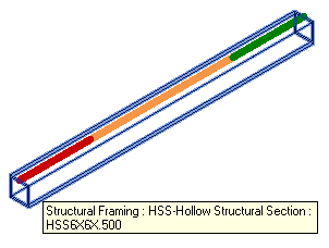
It is horizontal and oriented parallel to the Y axis:
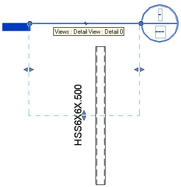
The CreateViewSection creates the a section view for it:
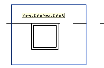
The section view displays its geometry including the internal loop for the hollow cavity:
2. Retrieve and analyse the cut plane faces of the element geometry.
Here is some code that demonstrates this, assuming the section view cutting the element is set up as described above:
  UIApplication uiapp = commandData.Application;
  UIDocument uidoc = uiapp.ActiveUIDocument;
  Application app = uiapp.Application;

  Document doc = Util.GetActiveDocument(
    uidoc, false );

  if( null == doc )
  {
    return Result.Failed;
  }

  // Retrieve pre-selected or
  // interactively select element

  Selection sel = uidoc.Selection;

  int n = sel.Elements.Size;

  if( 1 < n )
  {
    Util.InfoMessage( string.Format(
      "{0} element{1} selected. Please select one "
      + "single framing element for cross section "
      + "analysis.",
      n, Util.PluralSuffix( n ) ) );

    return Result.Failed;
  }

  Element e = null;

  if( 0 < n )
  {
    Debug.Assert( 1 == n,
      "we already checked for 1 < n above" );

    foreach( Element e2 in sel.Elements )
    {
      e = e2;
    }
  }
  else
  {
    try
    {
      Reference r = sel.PickObject(
        ObjectType.Element,
        "Please pick a framing element "
        + "for cross section analysis." );

      e = doc.GetElement( r.ElementId );
    }
    catch( RvtOperationCanceledException )
    {
      return Result.Cancelled;
    }
  }

  // Set up section view

  //ViewSection viewSection = GetFrontView( e );

  // Retrieve element solid

  Options opt = app.Create.NewGeometryOptions();

  //opt.IncludeNonVisibleObjects = true;

  // Cannot set both detail level and view:
  // Autodesk.Revit.Exceptions.InvalidOperationException
  // DetailLevel is already set. When DetailLevel is set
  // view-specific geometry can't be extracted.

  //opt.DetailLevel = DetailLevels.MAX;

  View view = doc.ActiveView;
  opt.View = view;

  //opt.View = viewSection;

  GeometryElement geo = e.get_Geometry( opt );
  GeometryInstance inst = null;

  foreach( GeometryObject obj in geo )
  {
    inst = obj as GeometryInstance;
    if( null != inst )
    {
      break;
    }
  }
  if( null == inst )
  {
    Util.InfoMessage( "Sorry, I am unable to retrieve "
      + "the structural framing geometry instance "
      + "from the selected element." );

    return Result.Failed;
  }
  Solid solid = null;

  //geo = inst.SymbolGeometry;
  geo = inst.GetInstanceGeometry();

  foreach( GeometryObject obj in geo )
  {
    solid = obj as Solid;

    if( null != solid
      && 0 != solid.Faces.Size )
    {
      break;
    }
  }

  // Select the first planar face which is
  // perpendicular to view direction, i.e. has
  // same normal vector as the view plane.
  // Assuming the cross section is constant,
  // any one will do. We expect two of them.

  XYZ viewDir = view.ViewDirection;

  PlanarFace crossSection = null;

  foreach( Face f in solid.Faces )
  {
    if( f is PlanarFace
      && Util.IsParallel( viewDir,
        ( f as PlanarFace ).Normal ) )
    {
      crossSection = f as PlanarFace;

      break;
    }
  }

  if( null == crossSection )
  {
    Util.InfoMessage( "Sorry, I am unable to retrieve "
      + "the structural framing cross section." );

    return Result.Failed;
  }

  EdgeArrayArray eaa = crossSection.EdgeLoops;

  n = eaa.Size;

  Debug.Print(
    "The selected structural framing element "
    + "cross section section view cut plane "
    + "face has {0} loop{1} and is thus '{2}'.",
    n, Util.PluralSuffix( n ),
    ( 1 == n ? "open" : "closed" ) );

  GeoSnoop.ShowCurve( "Solid face directly",
    eaa, AnalyticalDirection.Y );
It performs the following steps:
- Retrieve a pre-selected element or prompt one to be selected.
- Retrieve its geometry and drill down to a non-empty solid.
- Pick the first best face whose normal is parallel to the view direction.
The selected face represents the element cross section.
The number of loops indicates its topology, as explained above.
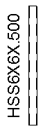
Here is a result of displaying the retrieved geometry in a custom 2D picture box using the GeoSnoop.ShowCurve method:
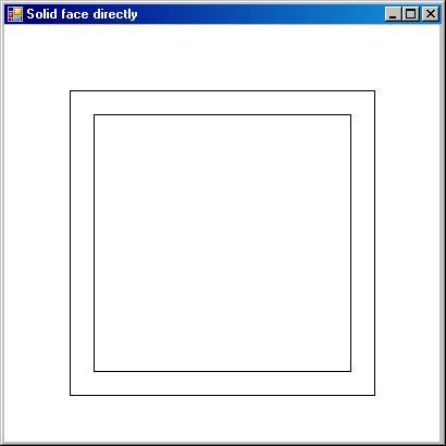
Here is the output from the add-in in the Visual Studio debug output window:
The selected structural framing element cross section section view cut plane face has 2 loops and is thus 'closed'.
Cross Section Analysis Using REX without the REX Framework
The REX content generator analysis is based on faces taken directly from the geometry, not the ExtrusionAnalyzer. It takes the GeometryElement and gathers all PlanarFaces according to a specific normal vector, taking the origin into consideration. That determines all loops. Next, the relations between them are determined.
The 'normal' way to use REX is to create a new Revit REX add-in from scratch using the REX add-in wizard.
I chose a different approach, because I wished to add the method to the add-in I already had.
Some additional steps are required to use this functionality independently of the REX module. In REX modules, they are performed automatically.
The REX.ContentGenerator component is not placed in the GAC or Revit directory, so .NET doesn’t know from where it should be loaded. There are several solutions:
- Provide REX.ContentGenerator.LT.dll in the same directory as your ExternalCommand, e.g. by using CopyLocal = true – not recommended.
- Load REX.ContentGenerator.LT at the beginning of ExternalCommand Execution – doable, but you have to know the correct path, which may be problematic.
- Use the Autodesk.Revit.Framework component to resolve assembly – this is a GAC assembly so .NET has no problem finding it.
The third solution is the most welcomed. Here what you should do:
- Add a reference to Autodesk.Revit.Framework.dll to your project (you can take it from GAC or from "\Program Files\Common Files\Autodesk Shared\Extensions 2014\Framework\Engine\AssemblyCache\Autodesk.REX.Framework.dll").
- Set copy local to False.
- Add the code which resolves the assembly, e.g. in the external command Execute method:
  AppDomain.CurrentDomain.AssemblyResolve
    += new ResolveEventHandler( OnAssemblyResolve );
Here is the method definition:
  static System.Reflection.Assembly OnAssemblyResolve(
    object sender,
    ResolveEventArgs args )
  {
    Assembly a = Assembly.GetExecutingAssembly();

    return Autodesk.REX.Framework.REXAssemblies
      .Resolve( sender, args, "2014", a );
  }
Note that the converter initialisation must reside in a different method than the subscription to the assembly resolver OnAssemblyResolve, because .NET investigates all methods before execution and will try to resolve the assembly before you register the resolving mechanism, which will cause a crash. The best way to avoid that is to create an additional method and call it separately, so you can register the resolve mechanism first.
Cross Section Analysis Using REX
Once REX is up and running, you have access to its functionality, and you know what classes and properties to query, there is hardly anything at all left to do.
Here is the entire RexXsecAnalyis method that identifies the framing member cross section type:
  /// <summary>
  /// Use REX to analyse element cross section.
  /// This requires a reference to
  /// REX.ContentGeneratorLT.dll and prior
  /// initialisation of the REX framework.
  /// The converter initialisation must reside in
  /// a different method than the subscription to
  /// the assembly resolver OnAssemblyResolve.
  /// </summary>
  void RexXsecAnalyis(
    ExternalCommandData commandData,
    Element e )
  {
    // Initialise converter

    RVTFamilyConverter rvt = new RVTFamilyConverter(
      commandData, true );

    // Retrieve family type

    REXFamilyType fam = rvt.GetFamily( e,
      ECategoryType.SECTION_PARAM );

    // Retrieve section data

    REXFamilyType_ParamSection paramSection = fam
      as REXFamilyType_ParamSection;

    REXSectionParamDescription parameters
      = paramSection.Parameters;

    // Extract dimensions, section type, tapered
    // predicate, etc.
    // If different start and end sections are
    // required, use DimensionsEnd as well.

    REXSectionParamDimensions dimensions = parameters
      .Dimensions;

    ESectionType sectionType = parameters
      .SectionType;

    bool tapered = parameters.Tapered;

    bool start = true;

    Contour_Section contour = parameters.GetContour(
      start );

    List<ContourCont> shape = contour.Shape;

    Debug.Print(
      "The selected structural framing element "
      + "cross section REX section type is "
      + "{0}.", sectionType );
  }
In this case, it prints the following message to the Visual Studio debug output window:
The selected structural framing element cross section REX section type is RECT_HOLLOW.
The REX documentation provides more information, e.g. on how to retrieve instance characteristics like area or moment of inertia. Here is a table of the supported sections with dimensions:
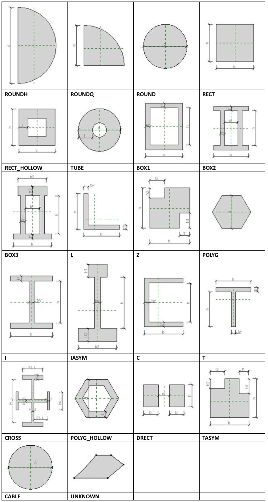
Note: In case of UNKNOWN, please use the contour directly, since no dimensions will be determined.
Migrating from Revit 2012 to Revit 2014
As said, all of my initial exploration of this was based on Revit 2012.
I easily migrated it to Revit 2014, though, and verified that it still works.
Here are all the code differences required for the migration:
Command.cs:

<   e = doc.get_Element( r.ElementId );
>   e = doc.GetElement( r.ElementId );

<   GeometryObjectArray objects = geo.Objects;
>   //GeometryObjectArray objects = geo.Objects;

<   foreach( GeometryObject obj in objects )
>   foreach( GeometryObject obj in geo )

<   objects = geo.Objects;
>   //objects = geo.Objects;

<   foreach( GeometryObject obj in objects )
>   foreach( GeometryObject obj in geo )

GeoSnoop.cs:

<   XYZ p = e.AsCurve().get_EndPoint( 0 );
<   XYZ p = e.AsCurve().GetEndPoint( 0 );
Not that much, is it?
The harder part was to browse to the REX .NET assemblies that I need to reference.
Here are all the Revit and REX .NET assembly references required for Revit 2014:
- Program Files\Autodesk\Revit 2014\RevitAPI.dll
- Program Files\Autodesk\Revit 2014\RevitAPIUI.dll
- Program Files\Common Files\Autodesk Shared\Extensions 2014\Framework\Components\AREXContentGenerator\REX.ContentGeneratorLT.dll
- Program Files\Common Files\Autodesk Shared\Extensions 2014\Framework\Engine\AssemblyCache\Autodesk.REX.Framework.dll
They can easily be listed by searching the C# project file for the DLL file name extension or the HintPath tag:
grep -i DLL FramingXsecAnalyzer.csproj
The initial test run threw an exception saying "Could not load file or assembly 'REX.ContentGeneratorLT, Version=2014.0.0.2608, Culture=neutral, PublicKeyToken=null' or one of its dependencies. The system cannot find the file specified."
That was resolved when I updated the crucial OnAssemblyResolve method, bumping the version number from 2012 to 2014:
  static System.Reflection.Assembly OnAssemblyResolve(
    object sender,
    ResolveEventArgs args )
  {
    Assembly a = Assembly.GetExecutingAssembly();

    return Autodesk.REX.Framework.REXAssemblies
      .Resolve( sender, args, "2014", a );
  }
I tested it on the following tubular column in Revit 2014 instead of a beam:
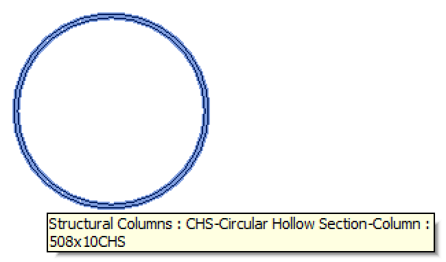
Here are the two resulting report messages from the pure Revit API and REX analysis, respectively:
The selected structural framing element cross section section view cut plane face has 2 loops and is thus 'closed'.
The selected structural framing element cross section REX section type is TUBE.
Obsolete GeoSnoop
This is actually the origin of the GeoSnoop .NET boundary curve loop visualisation, later updated for use with family symbols, that I make use of in the RoomEditorApp add-in for the simplified cloud-based 2D Revit model editing.
The RoomEditorApp version is significantly cleaned up, though, so please make sure to ignore the obsolete one provided here.
Download
I created a new FramingXsecAnalyzer GitHub repository to host this project, and published the following releases so far:
- 2012.0.0.0 – initial commit for Revit 2012
- 2014.0.0.0 – initial untested migration from Revit 2012 to Revit 2014
- 2014.0.0.1 – verified working functionality in Revit 2014