AU Day 1, Revit 2014 API Class, Keynote, DevLab and Rotated Bounding Box Rotation
AU Day 1, Revit 2014 API Class and Bounding Box Rotation
Tuesday was the first real day at AU after the DevDay pre-event conference yesterday.
Here are my main activities of the day in chronological order:
- Advanced Revit 2014 API features and samples
- AU Keynote by Jeff and Carl
- DevLab and bounding box rotation
- Adding a marker at the Revit project origin
- Download
Advanced Revit 2014 API Features and Samples
I presented my first class DV2010 – Advanced Revit 2014 API Features and Samples right away starting at the very first moment of AU, at eight in the morning.
Here is the most up-to-date handout and slide deck.
Keynote
As usual, the keynote presentation was given by Jeff Kowalski and Carl Bass, with Jeff focusing on ideas and long-term vision and Carl presenting real live usage examples of existing products.
Jeff expounded on the power and advantages of collaboration and open source, and how the Autodesk 360 platform supports that. He suggested picking a class by chance, to learn something completely new, mentioned reverse mentoring, where young people mentor older experienced folk, pointed out how much there is to learn from each other, e.g. using reverse innovation, consciously looking outside, beyond what you and everybody else thinks is possible, to learn, unlearn and relearn.
Carl highlighted a number of different original and creative companies making use of new technologies to save huge amounts of time and effort, e.g.:
- Orphanage guitars via fusion 360 to create custom made guitars involving the customer directly in the process.
- Aston Martin creating a new car, concept sketches, Sketchbook, Alias, CNC-generated clay model, post processed including hand sculpting, laser scanned to bring it back into Alias, completing the cycle to market in record time.
- PLM 360 cloud-based example with a four month adoption period, to search for data and create documentation
- Prosthetic leg collaboration project using A360 and CAM 360.
- Airport project complexity BIM developer share coordinate using BIM 360 Glue thousands of hours saved BIM 360 Field solve problems in real-time, Infraworks 360, ReCap point cloud image based 3D modelling, the only input you can really trust, saving thousands of hours of modelling work.
- BioLite building a stove scaled up by a factor of 500 from the normal design on short notice using SIM 360.
- Bot & Dolly film and robots Maya animate robots in real life the way you would normally animate virtual characters. Complete control of robot motion in time and space. Robot "Iris" danced for us. For a sample, look at Box on YouTube.
According to Carl, the most important things to look at in the coming days are Autodesk 360 and computational design, e.g. Dynamo. It currently drives Revit. Being open source, it can be adapted by anyone for other products as well, and an implementation driving Inventor has already been unveiled.
Lots of great new technology to discover, and more than 500 classes to choose from.
DevLab and Bounding Box Rotation
DevLab was active, lots of questions addressed.
One little issue I was able to capture was this snippet of code to calculate the max and min of a rotated bounding box, initially inspired by Angel Velez, Revit developer, and heavily edited by your humble scribe:
Angel pointed out that if you wish to calculate the result of rotating a bounding box representing a rectangle around the origin in the XY plane, you cannot simply rotate the min and max points, because the rotated max point may easily end up being 'smaller' in some coordinate than the rotated min.
One way to work around that is to extract all four bounding box corners, rotate each of them and determine new min and max values from those.
I implemented this little helper method to generate the four XY corner points of a bounding box, flattened onto its minimum Z elevation:
  /// <summary>
  /// Return the four XYZ corners of the given
  /// bounding box in the XY plane at the minimum
  /// Z elevation in the order lower left, lower
  /// right, upper right, upper left:
  /// </summary>
  public static XYZ[] GetCorners( BoundingBoxXYZ b )
  {
    double z = b.Min.Z;

    return new XYZ[] {
      new XYZ( b.Min.X, b.Min.Y, z ),
      new XYZ( b.Max.X, b.Min.Y, z ),
      new XYZ( b.Max.X, b.Max.Y, z ),
      new XYZ( b.Min.X, b.Max.Y, z )
    };
  }
In order to be able to use the standard .NET Min and Max methods to extract the min and max points from the rotated corners, I need to use a flavour of the XYZ point and vector class which implements the IComparable interface.
To obtain that, I implemented this little XyzComparable wrapper class:
  /// <summary>
  /// XYZ wrapper class implementing IComparable.
  /// </summary>
  class XyzComparable : XYZ, IComparable<XYZ>
  {
    public XyzComparable( XYZ a )
      : base( a.X, a.Y, a.Z )
    {
    }

    int IComparable<XYZ>.CompareTo( XYZ a )
    {
      return Util.Compare( this, a );
    }
  }
It makes use of my pre-existing XYZ Compare utility method:
  public static int Compare( XYZ p, XYZ q )
  {
    int d = Compare( p.X, q.X );

    if( 0 == d )
    {
      d = Compare( p.Y, q.Y );

      if( 0 == d )
      {
        d = Compare( p.Z, q.Z );
      }
    }
    return d;
  }
With all of that in place, the bounding box rotation ends up quite simple and readable:
  /// <summary>
  /// Return a rotated bounding box around
  /// the origin in the XY plane.
  /// We cannot just rotate the min and max points,
  /// because the rotated max point may easily end
  /// up being 'smaller' in some coordinate than the
  /// min. To work around that, we extract all four
  /// bounding box corners, rotate each of them and
  /// determine new min and max values from those.
  /// </summary>
  private static BoundingBoxXYZ RotateBoundingBox(
    BoundingBoxXYZ b,
    Transform t )
  {
    double height = b.Max.Z - b.Min.Z;

    // Four corners: lower left, lower right,
    // upper right, upper left:

    XYZ[] corners = Util.GetCorners( b );

    XyzComparable[] cornersTransformed
      = corners.Select<XYZ, XyzComparable>(
        p => new XyzComparable( t.OfPoint( p ) ) )
          .ToArray();

    b.Min = cornersTransformed.Min();
    b.Max = cornersTransformed.Max();
    b.Max += height * XYZ.BasisZ;

    return b;
  }
In order to test this new functionality, I dug up the old CmdBoundingBox implementation from The Building Coder samples, from one of the very first posts back in the year 2008.
It prompts you to select an element and used to just report its bounding box coordinates in a message box.
I modified that to draw model lines for the box instead, again making use of the GetCorners method defined above to extract the four vertices required. This also obviously requires changing the command's transaction mode from read-only to manual and adding a transaction, since the model line creation modifies the database.
To test the rotation functionality, I call the RotateBoundingBox method with a 60 degree rotation transformation and print and display the result like this:
public Result Execute(
  ExternalCommandData commandData,
  ref string message,
  ElementSet elements )
{
  UIApplication app = commandData.Application;
  UIDocument uidoc = app.ActiveUIDocument;
  Document doc = uidoc.Document;

  Element e = Util.SelectSingleElement(
    uidoc, "an element" );

  if( null == e )
  {
    message = "No element selected";
    return Result.Failed;
  }

  // Trying to call this property returns the
  // compile time error: Property, indexer, or
  // event 'BoundingBox' is not supported by
  // the language; try directly calling
  // accessor method 'get_BoundingBox( View )'

  //BoundingBoxXYZ b = e.BoundingBox[null];

  View v = null;

  BoundingBoxXYZ b = e.get_BoundingBox( v );

  if( null == b )
  {
    v = commandData.View;
    b = e.get_BoundingBox( v );
  }

  if( null == b )
  {
    Util.InfoMsg(
      Util.ElementDescription( e )
      + " has no bounding box." );
  }
  else
  {
    using( Transaction tx = new Transaction( doc ) )
    {
      tx.Start( "Draw Model Line Bounding Box Outline" );

      Debug.Assert( b.Transform.IsIdentity,
        "expected identity bounding box transform" );

      string in_view = ( null == v )
        ? "model space"
        : "view " + v.Name;

      Util.InfoMsg( string.Format(
        "Element bounding box of {0} in "
        + "{1} extends from {2} to {3}.",
        Util.ElementDescription( e ),
        in_view,
        Util.PointString( b.Min ),
        Util.PointString( b.Max ) ) );

      Creator creator = new Creator( doc );

      creator.DrawPolygon( new List<XYZ>(
        Util.GetCorners( b ) ) );

      Transform rotation = Transform.CreateRotation(
        XYZ.BasisZ, 60 * Math.PI / 180.0 );

      b = RotateBoundingBox( b, rotation );

      Util.InfoMsg( string.Format(
        "Bounding box rotated by 60 degrees "
        + "extends from {0} to {1}.",
        Util.PointString( b.Min ),
        Util.PointString( b.Max ) ) );

      creator.DrawPolygon( new List<XYZ>(
        Util.GetCorners( b ) ) );

      tx.Commit();
    }
  }
  return Result.Succeeded;
}
I tested that on a single wall element, with the following resulting model lines displaying the original and rotated bounding boxes:
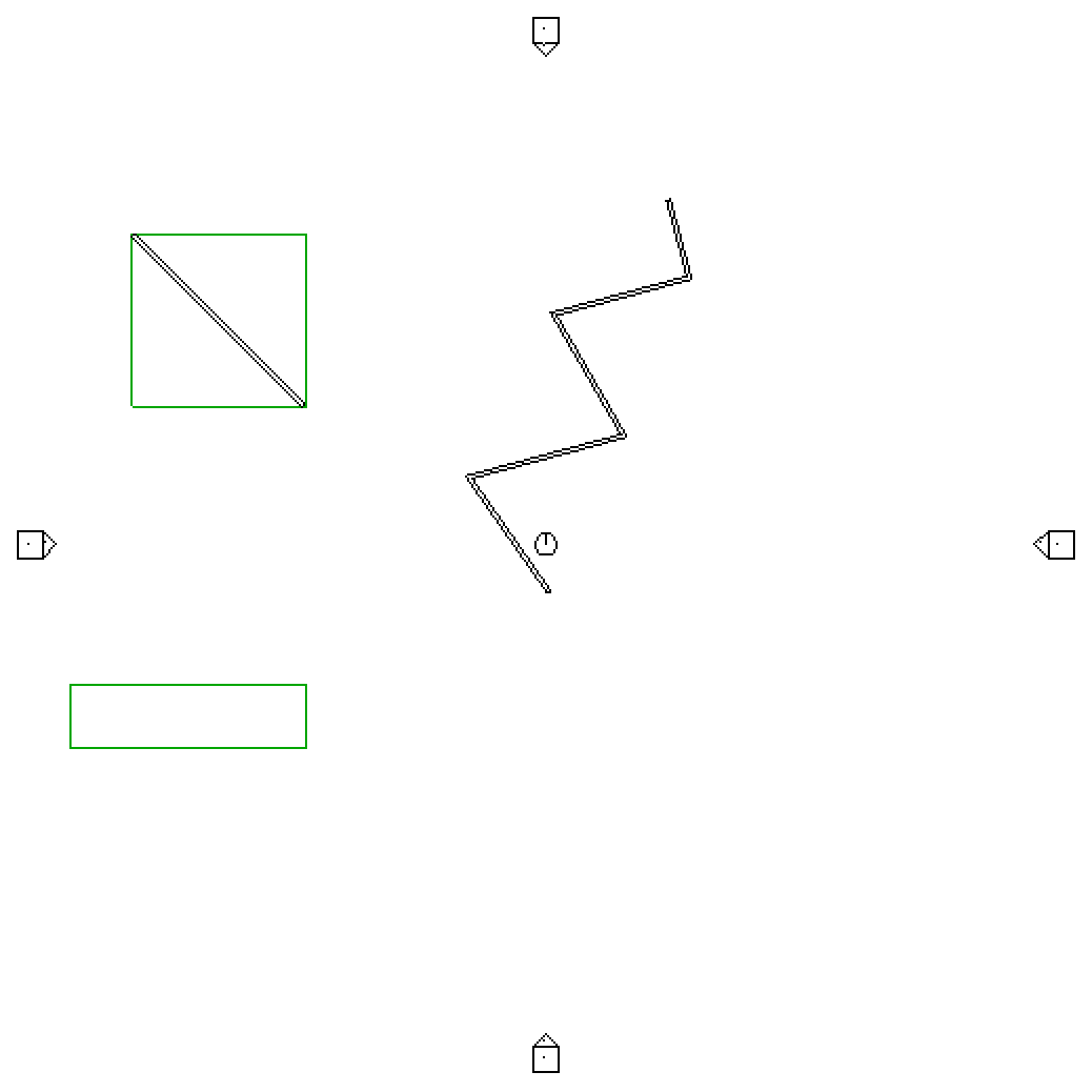
See how skewed it gets?
Addemdum by Angel Velez: this code assumes that the rotation is in XY only, hence the 'flattening' of the bounding box cube to 4 points. If you wanted to make it applicable to a truly arbitrary rotation, you would take the 8 points of the cube – so factor Min.Z and Max.Z into it – then you wouldn’t have to do any 'add Z back in at the end' hacks. Of course, you also have to do an extra 4 transforms.
That would add a significant amount of complecxity, however, and the above should cover the most common cases by far.
Adding a Marker at the Revit Project Origin
In order to understand properly and analyse the rotation results, we obviously need to know around which point it is taking place.
It would be handy to add a marker at a specific point in the Revit model, in this case at the origin.
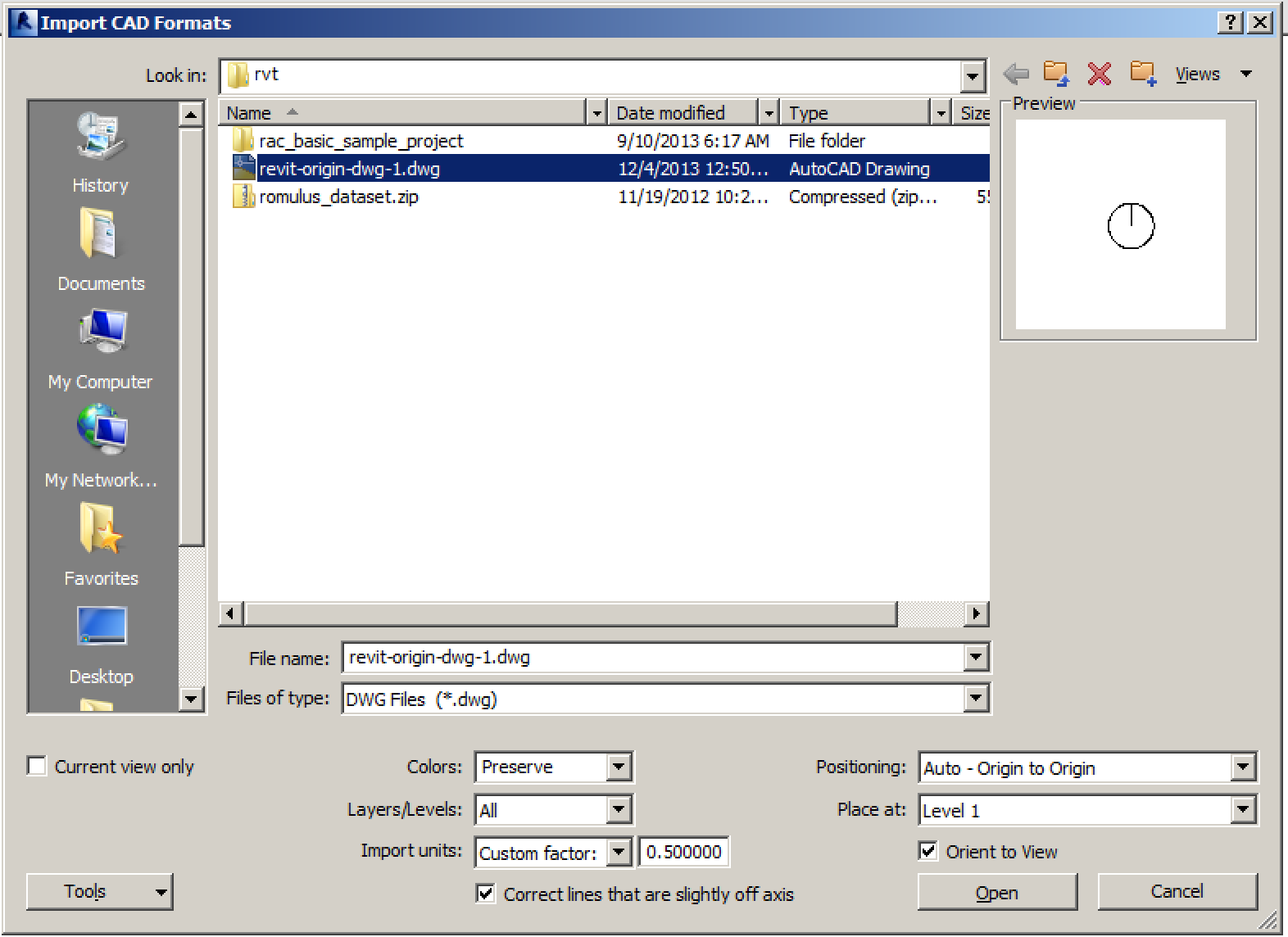
One way to achieve this, was described by the Revit Clinic discussing the two mile barrier: "If you want to be sure, the easiest method is to import a DWG file that contains a circle or X at AutoCAD's 0,0 and make sure to select the option origin-to-origin while importing the DWG file. This will show you exactly where the Revit origin is located (centre of the circle or x). Here is an AutoCAD file with a symbol at the origin."
When importing the DWG into my model using Insert > Import CAD, I left all the default setting values except the following:
- Import units: Custom factor: 0.5
- Positioning: Auto - Origin to Origin
You can admire the resulting origin marker in the screen snapshot above, along with model lines displaying the positions of the original and rotated bounding box.
Download
The updated version of this command is available from The Building Coder samples GitHub repository and the version discussed above is release 2014.0.106.0.
Have fun, and wish me a good quick sleep, since there are only a very few hours left before my next meeting...