Placing Equidistant Points Along a Curve
How can one generate equidistant points along a Revit curve element?
This is not completely trivial, since the Revit API only provides functionality to evaluate the curve based on its internal parameterisation, and not based on real world space coordinates.
I recently showed how to create a midcurve between two curve elements, also based on evaluating the two curves in their natural internal parameterisation space.
Now I looked at the task of placing equidistant points along a curve with the distance measured in real world coordinates instead of the curve parameterisation ones, prompted by the following developer query:
Question: I am trying to evaluate equidistant points on a NurbSpline. There is a method called Curve.Evaluate. It takes a parameter as input. I tried to use the following code to find the parameters to calculate the points at the required distances:
  double param1 = curve.GetEndParameter(0);
  double param2 = curve.GetEndParameter(1);

  double paramCalc = param1 + ((param2 - param1)
    * requiredDist / curveLength);

  XYZ evaluatedPoint = null;

  if (curve.IsInside(paramCalc))
  {
    double normParam = curve
      .ComputeNormalizedParameter(paramCalc);

    evaluatedPoint = curve.Evaluate(
      normParam, true)));
  }
This code works fine for Arc and Line, but not for splines.
It seems we may need to use the spline knots and weights for the NurbSpline calculations.
Is there any other way to evaluate the points at the required distances for NurbSpline?
I implemented a sample command that places equally spaced circles on a selected curve at distances of 5 feet. Here is one result of running it:
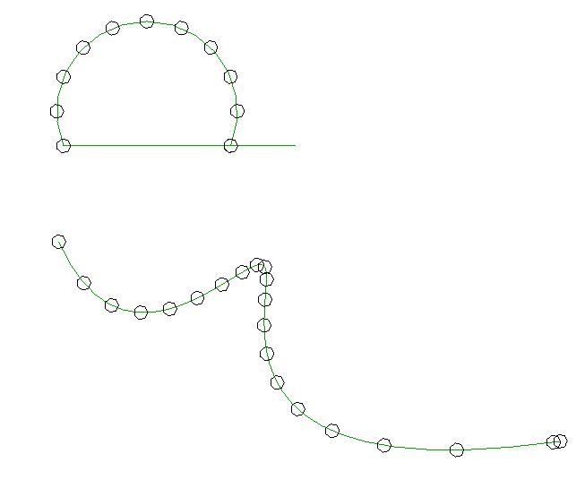
As you can see, the points on the arc are placed at the required distance, but not on the spline.
How can I solve this, please?
Answer: You will be glad to hear that this can be solved, and it is easy.
As said, I recently discussed generating a midcurve between two curve elements.
In that implementation, I move along the curve using a fixed step size in the curve parameter space.
Equal distances in the curve parameter space are transformed to non-equal distances in real world coordinates, especially when moving along a spline with sharp bends in it, as you discovered for yourself in your sample.
Determining points at equidistant positions along the curve, measured along the curve in real world coordinates instead of curve parameterisation coordinates, basically requires integration. You need to evaluate the curve step by step in very small increments and measure the sum of distances between the evaluation points until you reach the desired distance, then add a new marker point at that position.
If the number of intermediate vertices returned by the standard Revit API curve Tessellate method is sufficient, you could use those to step along the curve. If you require a higher precision, you can generate the intermediate integration points yourself using the curve Evaluate or ComputeDerivatives method.
I implemented a new external command named EquiDistantPointEval to test a simple implementation of this algorithm.
First, here is the helper method that I adapted from your sample to create the marker circles:
  /// <summary>
  /// Create a horizontal detail curve circle of
  /// the given radius at the specified point.
  /// </summary>
  DetailArc CreateCircle(
    Document doc,
    XYZ location,
    double radius )
  {
    XYZ norm = XYZ.BasisZ;

    double startAngle = 0;
    double endAngle = 2 * Math.PI;

    Plane plane = new Plane( norm, location );

    Arc arc = Arc.Create( plane,
      radius, startAngle, endAngle );

    return doc.Create.NewDetailCurve(
      doc.ActiveView, arc ) as DetailArc;
  }
With that in place, the external command performs the following steps:
- Prompt the user to select a curve element.
- Test its validity.
- Extract data from the selected curve.
- Create a list of equi-distant points along the curve.
- Place a marker circle at each point.
Here is the entire implementation of the external command Execute mainline method achieving this:
public Result Execute(
  ExternalCommandData commandData,
  ref string message,
  ElementSet elements )
{
  UIApplication uiapp = commandData.Application;
  UIDocument uidoc = uiapp.ActiveUIDocument;
  Document doc = uidoc.Document;

  Reference r = null;

  try
  {
    r = uidoc.Selection.PickObject(
      ObjectType.Element,
      new CurveSelectionFilter(),
      "Please pick an arc or spline to select path" );
  }
  catch( Autodesk.Revit.Exceptions
    .OperationCanceledException )
  {
    return Result.Cancelled;
  }

  if( null == r )
  {
    message = "Null pick object reference.";
    return Result.Failed;
  }

  Element e = doc.GetElement( r );

  if( null == e || !( e is CurveElement ) )
  {
    message = "Not a curve element.";
    return Result.Failed;
  }

  // Extract data from the selected curve.

  Curve curve = ( e as CurveElement ).GeometryCurve;

  IList<XYZ> tessellation = curve.Tessellate();

  // Create a list of equi-distant points.

  List<XYZ> pts = new List<XYZ>( 1 );

  double stepsize = 5.0;
  double dist = 0.0;

  XYZ p = curve.GetEndPoint( 0 );

  foreach( XYZ q in tessellation )
  {
    if( 0 == pts.Count )
    {
      pts.Add( p );
      dist = 0.0;
    }
    else
    {
      dist += p.DistanceTo( q );

      if( dist >= stepsize )
      {
        pts.Add( q );
        dist = 0;
      }
      p = q;
    }
  }

  // Place a marker circle at each point.

  using( Transaction tx = new Transaction( doc ) )
  {
    tx.Start( "Draw Curves at Points" );

    foreach( XYZ pt in pts )
    {
      CreateCircle( doc, pt, 1 );
    }
    tx.Commit();
  }
  return Result.Succeeded;
}
In its current state, it does not support straight lines properly. Since the tessellation of those returns just two points, it only places a marker at the start point, if it is shorter than the required distance, and at the start and end point, if it is longer.
Here is the result of running it in your sample model:
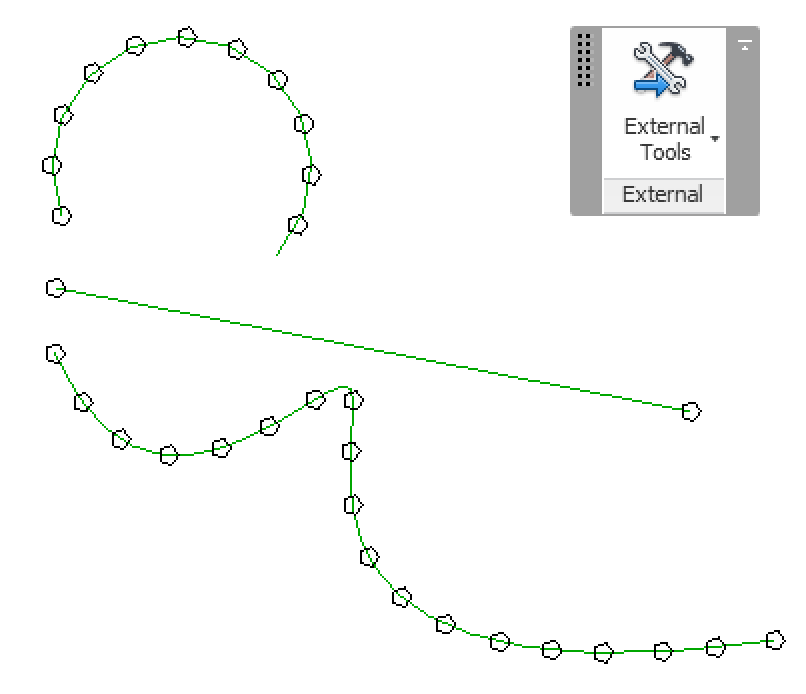
I hope this answers your question.
Here is EquiDistantPointEval.zip containing the full source code, Visual Studio solution and add-in manifest for this external command.
How to Unjoin Lines
Before we close for today, here is a note to highlight a neat trick that was just mentioned on the Autodesk discussion forum on the topic of unjoining lines:
"For model lines, I believe if you change one of the lines to a different workset it will cause it to be unjoined. Then you could move it back to the original workset."