Viewport Positioning and Conceptual Design Automation
Not all location relevant properties of viewports are currently accessible through the Revit API, which makes it slightly challenging to precisely define their position.
Let us look at a clever trick to align viewports exactly that works around that limitation, sheds some light on their location calculation and the modification of it that was made between Revit 2013 and 2014.
After that, I would like to briefly present a non-Revit-API BIM topic, a single-page MSc thesis overview on completely conceptual design automation, and mention the new Graitec technology acqusition.
Exact Viewport Positioning
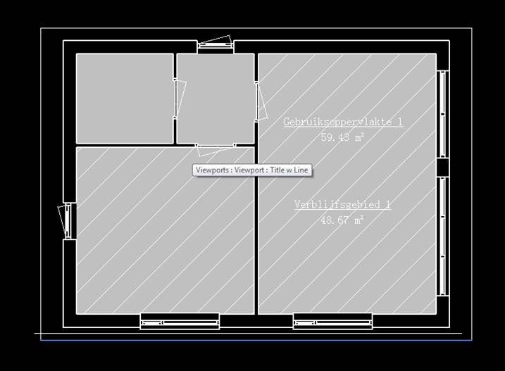
Question: I want to programmatically place views on a sheet and align them exactly with each other. In Revit 2013, my code works perfectly. I calculate the position of the view on the sheet from its crop box.
When I use the same calculation in Revit 2014, the insertion point is no longer correct.
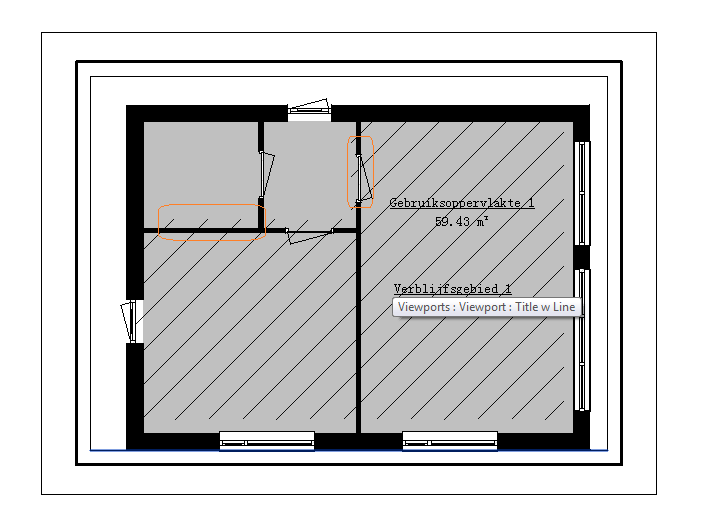
The view is placed centred according to the viewport instead of the view. The viewport location differs from the view one, because it depends on shown annotations and grid lines which extend the viewport, so my views are no longer aligned due to the different placing.
Here is the code to reproduce and demonstrate this behaviour using hard-coded element ids, so it will obviously only work in the specific test model:
public class ViewSheetTest1 : IExternalCommand
{
  public Result Execute(
    ExternalCommandData commandData,
    ref string message,
    ElementSet elements )
  {
    var doc = commandData.Application
      .ActiveUIDocument.Document;

    test2( doc );

    return Result.Succeeded;
  }

  private static void test2( Document doc )
  {
    FamilySymbol typ = doc.GetElement(
      new ElementId( 143899 ) ) as FamilySymbol;

    ViewPlan go1 = doc.GetElement(
      new ElementId( 205387 ) ) as ViewPlan;

    ViewPlan vg1 = doc.GetElement(
      new ElementId( 205424 ) ) as ViewPlan;

    var vSheet = ViewSheet.Create( doc, typ.Id );
    vSheet.Name = "test2";

    ElementId vid = vSheet.Id;
    var p = XYZ.Zero;

    var v12 = Viewport.Create( doc, vid, go1.Id, p );
    var v22 = Viewport.Create( doc, vid, vg1.Id, p );
  }
}
Here is the correct result produced in Revit 2013:
In Revit 2014, the viewport position is offset, as you can see from the highlighted hatch overlaps and gaps:
How can I solve this, please?
Is it possible to retrieve the coordinates of the view within the viewport, or is there some other possible solution for this?
Answer: The Viewport.Create method was fixed in 2014 to behave the way that was always documented – placement point being at the centre of the viewport. This was fixed because it was very difficult to lay out multiple views on a sheet where the viewport locations were determined by world coordinates and the size of the related view.
Unfortunately, you have encountered a drawback to this change – because many viewports will have a different centre relative to model coordinates, aligning them related to model coordinates is more difficult.
There is currently a gap in the API related to converting between model and sheet coordinates.
In the meantime, here is a workaround:
- Set the crop box for both views to be suitably large and identical.
- That will cause them to have identical viewport boundaries.
- You can therefore easily align them on the sheet.
- Then, restore the previous crop box settings.
Here is a function that does this for the two views in the original code:
void test4( Document doc )
{
  FamilySymbol typ = doc.GetElement(
    new ElementId( 143899 ) ) as FamilySymbol;

  ViewPlan go1 = doc.GetElement(
    new ElementId( 205387 ) ) as ViewPlan;

  ViewPlan vg1 = doc.GetElement(
    new ElementId( 205424 ) ) as ViewPlan;

  // Save current crop box values

  BoundingBoxXYZ savedBox1 = null;

  if( go1.CropBoxActive )
    savedBox1 = go1.CropBox;

  BoundingBoxXYZ savedBox2 = null;

  if( vg1.CropBoxActive )
    savedBox2 = vg1.CropBox;

  if( savedBox1 != null )
  {
    // Set crop box for 2nd view = 1st

    vg1.CropBox = savedBox1;
    vg1.CropBoxActive = true;
  }
  else
  {
    // Set both views to semi-random
    // but large crop box

    BoundingBoxXYZ newBox = new BoundingBoxXYZ();
    newBox.set_MinEnabled( 0, true );
    newBox.set_MinEnabled( 1, true );
    newBox.set_MinEnabled( 2, true );
    newBox.Min = new XYZ( -2000, -2000, 0 );
    newBox.set_MaxEnabled( 0, true );
    newBox.set_MaxEnabled( 1, true );
    newBox.set_MaxEnabled( 2, true );
    newBox.Max = new XYZ( 2000, 2000, 0 );

    vg1.CropBox = newBox;
    go1.CropBox = newBox;
    doc.Regenerate();
    vg1.CropBoxActive = true;
    go1.CropBoxActive = true;
  }

  doc.Regenerate();

  // Create sheets and viewports

  var vSheet = ViewSheet.Create( doc, typ.Id );
  vSheet.Name = "test3";

  ElementId vid = vSheet.Id;
  var p = XYZ.Zero;

  var v12 = Viewport.Create( doc, vid, go1.Id, p );
  var v22 = Viewport.Create( doc, vid, vg1.Id, p );

  doc.Regenerate();

  // Align lower left - works
  // because crop boxes are same

  Outline outline1 = v12.GetBoxOutline();
  Outline outline2 = v22.GetBoxOutline();

  XYZ min1 = outline1.MinimumPoint;
  XYZ min2 = outline2.MinimumPoint;

  XYZ diffToMove = min1 - min2;

  ElementTransformUtils.MoveElement(
    doc, v22.Id, diffToMove );

  doc.Regenerate();

  // Restore view crop boxes

  if( savedBox1 == null )
  {
    go1.CropBoxActive = false;
  }
  else
  {
    go1.CropBox = savedBox1;
    go1.CropBoxActive = true;
    go1.CropBoxVisible = false;
  }

  if( savedBox2 == null )
  {
    vg1.CropBoxActive = false;
  }
  else
  {
    vg1.CropBox = savedBox2;
    vg1.CropBoxActive = true;
    vg1.CropBoxVisible = false;
  }
}
Response: The suggested workaround works like a charm. :-)
I still have a question regarding your statement "... because many viewports will have a different centre relative to model coordinates": how does Revit internally calculate the centre of a viewport? Is that controlled by the CropBox property value?
Answer: The viewport size is governed by both the annotation crop box and the model crop box at different times, depending on which is larger. Currently, the API only provides access to the model crop box.
Therefore, making the model crop box large enough (where 'enough' is not a very precise term) seems to help. When it is too small, the annotations in one of the views causes the mismatch you observed.
Response: I am happy to inform you that I have tested your workaround in a couple of scenarios in our main application and it continues to work
Conceptual Design Automation Thesis
Ritchie Jackson of the Adaptive Architecture and Computation programme at UCL, the University College London, provided several valuable contributions to this blog in the past and now completed his MSc. thesis on Conceptual Design Automation including this single-page complete overview:
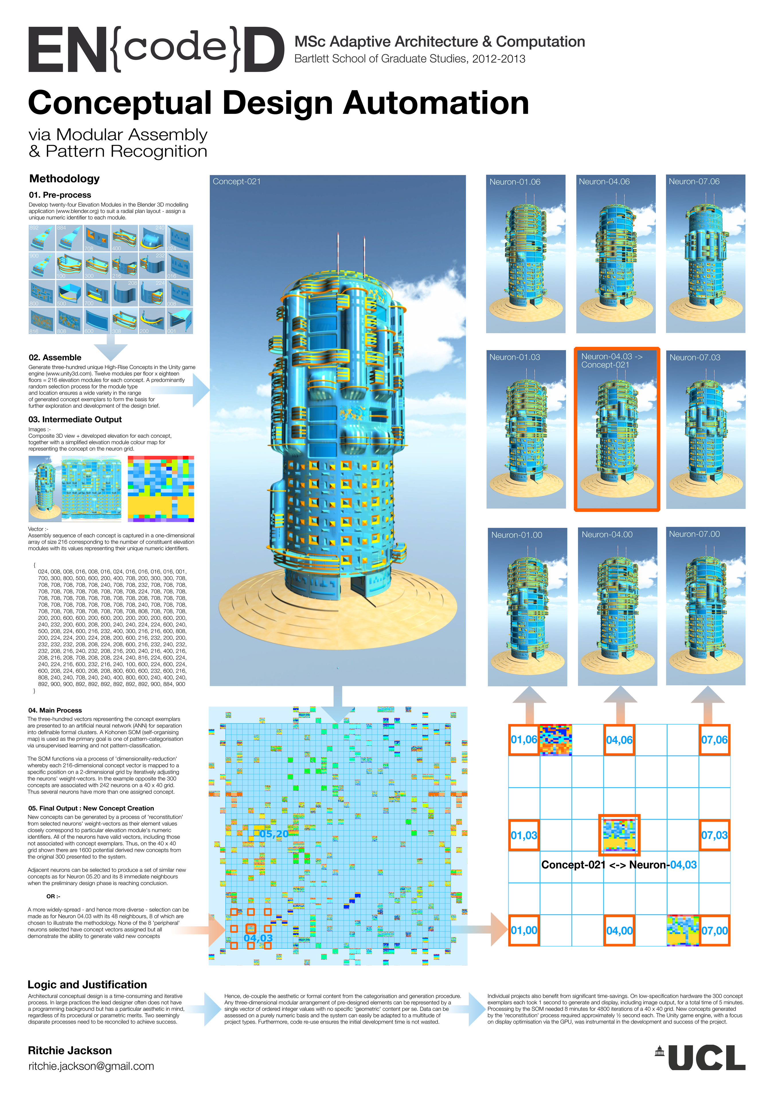
It was implemented using the Unity game engine, C# and a neural network to facilitate the automation of the conceptual design process, so with no Revit API involvement.
Here is a short Q&A between me and Ritchie to gain better understanding:
Questions: After reading the text, I do not understand where the neural network enters into the picture, or what has been optimised or learned by the machine in the process. To me, it looks like random input and random output.
- What is the non-random part?
- What is the target or goal?
- What has been optimised or improved?
Answers:
- Random input only – for modular assembly.
- Non-random is the concept categorisation process by the neural network into definable clusters – aesthetic in this case.
- Goal is to reconstitute similar unique concepts from a preferred cluster once unsupervised learning is complete.
- The network is able to produce viable concepts far more quickly than traditional 'manual' CAD techniques.
Questions:
- How does the unsupervised learning work?
- Where is the supervised learning in this process?
- How do you identify viable concepts?
- What in an unviable concept?
Answers:
- Unsupervised learning works by finding patterns rather than matching them.
- There is no supervised learning as there are no specific pre-defined modular arrangements to be targeted.
- Viable concepts, in this particular case, are those that meet the designer's aesthetic preferences.
- Conversely, unviable concepts are those that don't.
In addition: –
- Machines are more capable than humans at swiftly producing serendipitous outcomes.
Many thanks to Ritchie for sharing this, and especially for the nice wording of the final conclusion :-)
Autodesk Acquires Additional Structural Engineering Knowhow
To close, a piece of breaking news: Autodesk has signed an agreement to acquire Graitec technology, including the Advance Steel and Advance Concrete product lines, and associated employees, thus expanding its BIM portfolio for structural fabrication and detailing.
Addendum: Here are new links to the new Advance Steel and Advance Concrete product centers: