Generating a MidCurve Between Two Curve Elements
Here is a fun little geometric issue raised by Bang in his or her comment on Revit curves and their parameterisation, and also discussed quite extensively in this discussion thread on how to create middle/centre curve between two curves:
Question: How to determine the curve centre between two curves, e.g. between:
- Arc – Arc
- Circle – Arc
- Elliptical arc – Ellipse
- Ellipse – Ellipse
- NURBS – NurbSpline
- Hermite – HermiteSpline
Answer: That is a nice geometrical question you have.
The Revit Geometry API does not provide direct support for that functionality, so you would have to implement it yourself.
The Revit curve class does however provide some very nice completely generic features to access the underlying curve parameterisation.
That makes it very easy to implement this by generating approximating straight line segments between the two curves.
You can query the two original curves for their underlying parametric definition data, calculate matching pairs of intermediate points along the two curves, and then generate straight line segments between the midpoints of matching pairs.
It is much more difficult to calculate an exact non-approximating curve between the two given ones, though.
This approximation approach is also suggested and used in the discussion thread on how to create middle/centre curve between two curves.
Seeing as I love little geometrical issues like this, I decided to go ahead and tackle it myself, and add it as a new command CmdMidCurve to The Building Coder samples.
This is the first new command added in the Revit 2014 time frame.
The command basically consists of three parts:
- User interface to select two curve elements.
- Determine curve parameterisation data.
- Generate approximating midcurve model line segments.
User Interface to Select Two Curve Elements
As usual, the user interface takes up more code than the real processing functionality.
In this case, we request the selection of the two curve elements to start out from.
I always like to implement my user interface in a manner that simplifies testing as far as possible.
For instance, it helps if no interactive selection is required in my testing model.
This led me to implement the following selection algorithm:
- Retrieve all curve elements in the entire model.
- If there are exactly two, use those directly with no further questions asked.
- If there are less than two, there is nothing we can do, so bail out.
- If there are more than two, and two or more have been pre-selected before launching the command, use the first two encountered in the selection set.
- Otherwise, prompt for interactive post-selection of the two curve elements using an appropriate selection filter.
Here is what this looks like in my implementation:
[Transaction( TransactionMode.Manual )]
class CmdMidCurve : IExternalCommand
{
  /// <summary>
  /// Number of approximation segments to generate.
  /// </summary>
  const int _nSegments = 64;

  const string _prompt
    = "Please run this in a model containing "
    + "exactly two curve elements, and they will be "
    + "automatically selected. Alternatively, pre-"
    + "select two curve elements before launching "
    + "this command, or post-select them when "
    + "prompted.";

  /// <summary>
  /// Allow selection of curve elements only.
  /// </summary>
  class CurveElementSelectionFilter : ISelectionFilter
  {
    public bool AllowElement( Element e )
    {
      return e is CurveElement;
    }

    public bool AllowReference( Reference r, XYZ p )
    {
      return true;
    }
  }

  public Result Execute(
    ExternalCommandData commandData,
    ref string message,
    ElementSet elements )
  {
    UIApplication uiapp = commandData.Application;
    UIDocument uidoc = uiapp.ActiveUIDocument;
    Application app = uiapp.Application;
    Document doc = uidoc.Document;

    // Select all model curves in the entire model.

    List<CurveElement> curves = new List<CurveElement>(
      new FilteredElementCollector( doc )
        .OfClass( typeof( CurveElement ) )
        .ToElements()
        .Cast<CurveElement>() );

    int n = curves.Count;

    // If there are less than two,
    // there is nothing we can do.

    if( 2 > n )
    {
      message = _prompt;
      return Result.Failed;
    }

    // If there are exactly two, pick those.

    if( 2 < n )
    {
      // Else, check for a pre-selection.

      curves.Clear();

      Selection sel = uidoc.Selection;

      n = sel.Elements.Size;

      Debug.Print( "{0} pre-selected elements.",
        n );

      // If two or more model curves were pre-
      // selected, use the first two encountered.

      if( 1 < n )
      {
        foreach( Element e in sel.Elements )
        {
          CurveElement c = e as CurveElement;

          if( null != c )
          {
            curves.Add( c );

            if( 2 == curves.Count )
            {
              Debug.Print( "Found two model curves, "
                + "ignoring everything else." );

              break;
            }
          }
        }
      }

      // Else, prompt for an
      // interactive post-selection.

      if( 2 != curves.Count )
      {
        curves.Clear();

        try
        {
          Reference r = sel.PickObject(
            ObjectType.Element,
            new CurveElementSelectionFilter(),
            "Please pick first model curve." );

          curves.Add( doc.GetElement( r.ElementId )
            as CurveElement );
        }
        catch( Autodesk.Revit.Exceptions
          .OperationCanceledException )
        {
          return Result.Cancelled;
        }

        try
        {
          Reference r = sel.PickObject(
            ObjectType.Element,
            new CurveElementSelectionFilter(),
            "Please pick second model curve." );

          curves.Add( doc.GetElement( r.ElementId )
            as CurveElement );
        }
        catch( Autodesk.Revit.Exceptions
          .OperationCanceledException )
        {
          return Result.Cancelled;
        }
      }
    }

    // . . .

    return Result.Succeeded;
  }
}
Determine Curve Parameterisation Data
The generic curve parameterisation data that we need is simple: just the start and end parameter defining the range interval and the step size to traverse it, depending on the number of segments to generate, for each of the two curves:
  // Extract data from the two selected curves.

  Curve c0 = curves[0].GeometryCurve;
  Curve c1 = curves[1].GeometryCurve;

  double sp0 = c0.GetEndParameter( 0 );
  double ep0 = c0.GetEndParameter( 1 );
  double step0 = ( ep0 - sp0 ) / _nSegments;

  double sp1 = c1.GetEndParameter( 0 );
  double ep1 = c1.GetEndParameter( 1 );
  double step1 = ( ep1 - sp1 ) / _nSegments;

  Debug.Print( "Two curves' step size [start, end]:"
    + " {0} [{1},{2}] -- {3} [{4},{5}]",
    Util.RealString( step0 ),
    Util.RealString( sp0 ),
    Util.RealString( ep0 ),
    Util.RealString( step1 ),
    Util.RealString( sp1 ),
    Util.RealString( ep1 ) );
Generate Approximating Midcurve Model Line Segments
We use the curve Evaluate method to determine matching pairs of intermediate curve points on each of the two curves.
We determine the midpoint between each pair, and connect those with line segments to approximate the midcurve.
An assertion verifies that the result of Evaluate at the start parameter value equals the curve start point returned by GetEndPoint(0).
  // Modify document within a transaction.

  using( Transaction tx = new Transaction( doc ) )
  {
    Creator creator = new Creator( doc );

    tx.Start( "MidCurve" );

    // Current segment start points.

    double t0 = sp0;
    double t1 = sp1;

    XYZ p0 = c0.GetEndPoint( 0 );
    XYZ p1 = c1.GetEndPoint( 0 );
    XYZ p = Util.Midpoint( p0, p1 );

    Debug.Assert(
      p0.IsAlmostEqualTo( c0.Evaluate( t0, false ) ),
      "expected equal start points" );

    Debug.Assert(
      p1.IsAlmostEqualTo( c1.Evaluate( t1, false ) ),
      "expected equal start points" );

    // Current segment end points.

    t0 += step0;
    t1 += step1;

    XYZ q0, q1, q;
    Line line;

    for( int i = 0; i < _nSegments; ++i, t0 += step0, t1 += step1 )
    {
      q0 = c0.Evaluate( t0, false );
      q1 = c1.Evaluate( t1, false );
      q = Util.Midpoint( q0, q1 );

      Debug.Print(
        "{0} {1} {2} {3}-{4} {5}-{6} {7}-{8}",
        i,
        Util.RealString( t0 ),
        Util.RealString( t1 ),
        Util.PointString( p0 ),
        Util.PointString( q0 ),
        Util.PointString( p1 ),
        Util.PointString( q1 ),
        Util.PointString( p ),
        Util.PointString( q ) );

      // Create approximating curve segment.

      line = Line.CreateBound( p, q );
      creator.CreateModelCurve( line );

      p0 = q0;
      p1 = q1;
      p = q;
    }
    tx.Commit();
  }
Test Model
Here is a sample model to test this in:
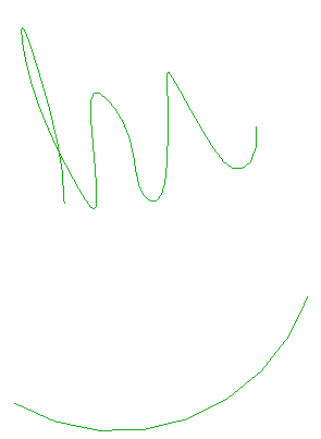
The top curve is a spline, and the bottom one a simple arc.
The two selected curve parameterisations are completely different in this case, generating the following start to end intervals and step sizes for 64 segments:
| Start | End | Step size |
|---|---|---|
| 0.0 | 444.1 | 6.94 |
| 4.18 | 5.94 | 0.03 |
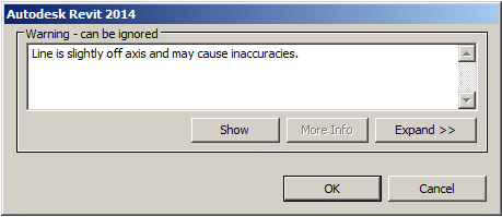
Executing the command generates a warning message before it terminates, which can be ignored:
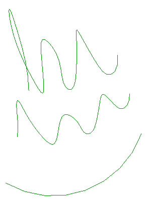
The resulting midcurve approximation looks all right to me:
Download
Here is version 2014.0.101.0 of The Building Coder samples source code, Visual Studio solution and RvtSamples include file including the new CmdMidCurve command.
I hope you find this useful and thank Bang for raising this issue.