Room and Furniture Loops Using Symbols
Continuing the research and development for my cloud-based round-trip 2D Revit model editing project, I now implemented the first of the next steps mentioned at the end:
- Separation of symbol and instance data in my add-in and database structure: currently, the furniture loops are placed absolutely, and multiple instances of a symbol duplicate the same loop over and over again at different locations. I will rewrite this to separate the furniture loop definition, defined by the family symbol, and its placement, defined by the instance. This needs to be done anyway to enable editing the placement data through the editor interaction on the mobile device.
The first implementation just uploaded the room and furniture instance 2D boundary polygon loops, absolutely placed.
Besides converting that to defining and reusing symbols, I also added support for exporting the model and level data to the cloud.
I discuss the implementation of that here now:
- Database structure
- Database upload
- Integer based 2D placement
- Populating symbols and instances
- Retrieving the boundary loops
- GeoSnoop loop display
- Caveats
- Download
- Next steps
Database Structure
I enhanced the database classes to include a new class DbSymbol. It defines the family symbol loop, which is reused by the family instances.
The DbFurniture class no longer has its own individual loop data. Instead, it has a reference to a symbol and placement data defining its 2D translation and rotation.
All the database classes are derived from the DbObj base class:
- DbObj
- Type
- Description
- Name
Some of the derived classes have no additional properties of their own at all. The data structure is this as simple as this:
- DbModel
- DbLevel
- ModelId
- DbRoom
- LevelId
- Loops
- ViewBox
- DbSymbol
- Loop
- DbFurniture
- RoomId
- SymbolId
- Transform
The source code does nothing but exactly reproduce this structure. Here is the complete implementation of these classes:
  /// <summary>
  /// Base class for all Jeremy Room Editor classes.
  /// </summary>
  class DbObj : CouchDocument
  {
    protected DbObj()
    {
      Type = "obj";
    }
    public string Type { get; protected set; }
    public string Description { get; set; }
    public string Name { get; set; }
  }

  /// <summary>
  /// Current model, i.e. Revit project.
  /// </summary>
  class DbModel : DbObj
  {
    public DbModel()
    {
      Type = "model";
    }
  }

  /// <summary>
  /// Level.
  /// </summary>
  class DbLevel : DbObj
  {
    public DbLevel()
    {
      Type = "level";
    }
    public string ModelId { get; set; }
  }

  /// <summary>
  /// Room
  /// </summary>
  class DbRoom : DbObj
  {
    public DbRoom()
    {
      Type = "room";
    }
    public string LevelId { get; set; }
    public string Loops { get; set; }
    public string ViewBox { get; set; }
  }

  /// <summary>
  /// Family symbol, i.e. element type defining
  /// the geometry, i.e. the 2D boundary loop.
  /// </summary>
  class DbSymbol : DbObj
  {
    public DbSymbol()
    {
      Type = "symbol";
    }
    public string Loop { get; set; }
  }

  /// <summary>
  /// Family instance, defining placement, i.e.
  /// transform, i.e. translation and rotation,
  /// and referring to the symbol geometry.
  /// </summary>
  class DbFurniture : DbObj
  {
    public DbFurniture()
    {
      Type = "furniture";
    }
    public string RoomId { get; set; }
    public string SymbolId { get; set; }
    public string Transform { get; set; }
  }
Database Upload
The database upload has not changed very much from the previous version, except that the model, level and symbol data is now added, and the furniture and equipment instances store their symbol reference and transformation:
/// <summary>
/// Upload model, level, room and furniture data
/// to an IrisCouch hosted CouchDB data repository.
/// </summary>
static public void DbUploadRoom(
  Room room,
  List<Element> furniture,
  JtLoops roomLoops,
  Dictionary<string, JtLoop> furnitureLoops,
  List<JtPlacement2dInt> furnitureInstances )
{
  CouchClient client = new CouchClient(
    _web_url,
    5984 );

  CouchDatabase db = client.GetDatabase(
    _database_name, true );

  Document doc = room.Document;

  Element projectInfo
    = new FilteredElementCollector( doc )
      .OfClass( typeof( ProjectInfo ) )
      .FirstElement();

  string uid = projectInfo.UniqueId;

  DbModel dbModel;

  if( db.DocumentExists( uid ) )
  {
    dbModel = db.GetDocument<DbModel>( uid );

    Debug.Assert(
      dbModel.Id.Equals( projectInfo.UniqueId ),
      "expected equal ids" );

    dbModel.Description = Util.ElementDescription(
      projectInfo );

    dbModel.Name = projectInfo.Document.Title;

    dbModel = db.UpdateDocument<DbModel>(
      dbModel );
  }
  else
  {
    dbModel = new DbModel();

    dbModel.Id = uid;
    dbModel.Description = Util.ElementDescription(
      projectInfo );

    dbModel.Name = projectInfo.Name;
    dbModel = db.CreateDocument<DbModel>( dbModel );
  }

  Level level = room.Level;

  uid = level.UniqueId;

  DbLevel dbLevel;

  if( db.DocumentExists( uid ) )
  {
    dbLevel = db.GetDocument<DbLevel>( uid );

    Debug.Assert(
      dbLevel.Id.Equals( level.UniqueId ),
      "expected equal ids" );

    dbLevel.Description = Util.ElementDescription(
      level );

    dbLevel.Name = level.Name;
    dbLevel.ModelId = projectInfo.UniqueId;

    dbLevel = db.UpdateDocument<DbLevel>(
      dbLevel );
  }
  else
  {
    dbLevel = new DbLevel();

    dbLevel.Id = uid;
    dbLevel.Description = Util.ElementDescription(
      level );

    dbLevel.Name = level.Name;
    dbLevel.ModelId = projectInfo.UniqueId;

    dbLevel = db.CreateDocument<DbLevel>(
      dbLevel );
  }

  uid = room.UniqueId;

  DbRoom dbRoom;

  if( db.DocumentExists( uid ) )
  {
    dbRoom = db.GetDocument<DbRoom>( uid );

    Debug.Assert(
      dbRoom.Id.Equals( room.UniqueId ),
      "expected equal ids" );

    dbRoom.Description = Util.ElementDescription(
      room );

    dbRoom.Name = room.Name;
    dbRoom.LevelId = level.UniqueId;
    dbRoom.Loops = roomLoops.SvgPath;
    dbRoom.ViewBox = roomLoops.BoundingBox.SvgViewBox;

    dbRoom = db.UpdateDocument<DbRoom>( dbRoom );
  }
  else
  {
    dbRoom = new DbRoom();

    dbRoom.Id = uid;
    dbRoom.Description = Util.ElementDescription(
      room );

    dbRoom.Name = room.Name;
    dbRoom.LevelId = level.UniqueId;
    dbRoom.Loops = roomLoops.SvgPath;
    dbRoom.ViewBox = roomLoops.BoundingBox.SvgViewBox;

    dbRoom = db.CreateDocument<DbRoom>( dbRoom );
  }

  foreach( KeyValuePair<string, JtLoop> p in furnitureLoops )
  {
    uid = p.Key;
    Element e = doc.GetElement( uid );
    if( db.DocumentExists( uid ) )
    {
      DbSymbol symbol = db.GetDocument<DbSymbol>(
        uid );

      symbol.Description = Util.ElementDescription( e );
      symbol.Name = e.Name;
      symbol.Loop = p.Value.SvgPath;

      symbol = db.UpdateDocument<DbSymbol>( symbol );
    }
    else
    {
      DbSymbol symbol = new DbSymbol();
      symbol.Id = uid;
      symbol.Description = Util.ElementDescription( e );
      symbol.Name = e.Name;
      symbol.Loop = p.Value.SvgPath;

      symbol = db.CreateDocument<DbSymbol>( symbol );
    }
  }

  foreach( FamilyInstance f in furniture )
  {
    uid = f.UniqueId;
    if( db.DocumentExists( uid ) )
    {
      DbFurniture dbf = db.GetDocument<DbFurniture>(
        uid );

      dbf.Description = Util.ElementDescription( f );
      dbf.Name = f.Name;
      dbf.RoomId = room.UniqueId;
      dbf.SymbolId = f.Symbol.UniqueId;
      dbf.Transform = new JtPlacement2dInt( f )
        .SvgTransform;

      dbf = db.UpdateDocument<DbFurniture>( dbf );
    }
    else
    {
      DbFurniture dbf = new DbFurniture();
      dbf.Id = uid;
      dbf.Description = Util.ElementDescription( f );
      dbf.Name = f.Name;
      dbf.RoomId = room.UniqueId;
      dbf.SymbolId = f.Symbol.UniqueId;
      dbf.Transform = new JtPlacement2dInt( f )
        .SvgTransform;

      dbf = db.CreateDocument<DbFurniture>( dbf );
    }
  }
}
Integer Based 2D Placement
I implemented the following simple class to manage the 2D placement.
It is based on the 2D point class, storing the coordinate data in integers, for various reasons:
- Revit precision is no smaller than one sixteenth of an inch, ca. 1.2 mm.
- The data is stored in the cloud and rendered on a mobile device: the use of integers
- eliminates rounding issues,
- lowers the data volume,
- enhances performance,
- simplifies storage,
- improves human reading and understanding.
Since I am already using millimetres for the length measurement, I find it fitting to store the rotation in degrees. The SVG rendering expects degrees as input, anyway.
Here is the class implementation:
/// <summary>
/// A 2D integer-based transformation,
/// i.e. translation and rotation.
/// </summary>
class JtPlacement2dInt
{
  /// <summary>
  /// Translation.
  /// </summary>
  public Point2dInt Translation { get; set; }

  /// <summary>
  /// Rotation in degrees.
  /// </summary>
  public int Rotation { get; set; }

  /// <summary>
  /// The family symbol UniqueId.
  /// </summary>
  public string SymbolId { get; set; }

  public JtPlacement2dInt( FamilyInstance fi )
  {
    LocationPoint lp = fi.Location as LocationPoint;

    Debug.Assert( null != lp,
      "expected valid family instanace location point" );

    Translation = new Point2dInt( lp.Point );

    Rotation = (int) (
      ( ( 180 * lp.Rotation ) + 0.5 ) / Math.PI );

    SymbolId = fi.Symbol.UniqueId;
  }

  /// <summary>
  /// Return an SVG transform,
  /// either for native SVG or Raphael.
  /// </summary>
  public string SvgTransform
  {
    get
    {
      return string.Format(
        "R{2}T{0},{1}",
        //"translate({0},{1}) rotate({2})",
        Translation.X, Translation.Y, Rotation );
    }
  }
}
The placement is instantiated from a family instance, and returns a suitably formatted SVG transformation string, either for native SVG or the Raphaël JavaScript SVG library.
Populating Symbols and Instances
To populate the symbol and instance data, I loop over all the instances exactly like I did previously.
Now, instead of exporting the family instance boundary loop in situ, I transform it back to the symbol definition coordinate system instead, and save that in a dictionary mapping the family symbol UniqueId to its boundary loop.
The family instance exports a reference to that symbol and its placement data:
  List<Element> furniture
    = GetFurniture( room );

  // Map symbol UniqueId to symbol loop

  Dictionary<string, JtLoop> furnitureLoops
    = new Dictionary<string, JtLoop>();

  // List of instances referring to symbols

  List<JtPlacement2dInt> furnitureInstances
    = new List<JtPlacement2dInt>(
      furniture.Count );

  int nFailures;

  foreach( FamilyInstance f in furniture )
  {
    FamilySymbol s = f.Symbol;

    string uid = s.UniqueId;

    if( !furnitureLoops.ContainsKey( uid ) )
    {
      nFailures = 0;

      JtLoops loops = GetPlanViewBoundaryLoops(
        f, ref nFailures );

      if( 0 < nFailures )
      {
        Debug.Print( "{0}: {1} extrusion analyser failure{2}",
          Util.ElementDescription( f ), nFailures,
          Util.PluralSuffix( nFailures ) );
      }
      ListLoops( f, loops );

      if( 0 < loops.Count )
      {
        // Assume first loop is outer one

        furnitureLoops.Add( uid, loops[0] );
      }
    }
    furnitureInstances.Add(
      new JtPlacement2dInt( f ) );
  }
Retrieving the Boundary Loops
The boundary loop retrieval has not changed very much, although the following significant enhancements were made:
- Store the symbol loop in the original symbol definition coordinate system.
- Store the instance transformation data.
- Manage the dictionary of symbols and the instances referencing them.
- Save intermediate tessellated curve points, not just start and end point. This functionality can be toggled on and off by setting the Boolean _tessellate_curves switch.
The implementation is separated into two methods:
- AddLoops: add the plan view boundary loops from a given solid to the list of loops.
- GetPlanViewBoundaryLoops: Retrieve the plan view boundary loops from all solids of given element united together. If the element is a family instance, transform its loops from the instance placement coordinate system back to the symbol definition one.
Here is the implementation:
/// <summary>
/// Add all plan view boundary loops from
/// given solid to the list of loops.
/// The creation application argument is used to
/// reverse the extrusion analyser output curves
/// in case they are badly oriented.
/// </summary>
/// <returns>Number of loops added</returns>
int AddLoops(
  Autodesk.Revit.Creation.Application creapp,
  JtLoops loops,
  GeometryObject obj,
  ref int nExtrusionAnalysisFailures )
{
  int nAdded = 0;

  Solid solid = obj as Solid;

  if( null != solid
    && 0 < solid.Faces.Size )
  {
    Plane plane = new Plane( XYZ.BasisX,
      XYZ.BasisY, XYZ.Zero );

    ExtrusionAnalyzer extrusionAnalyzer = null;

    try
    {
      extrusionAnalyzer = ExtrusionAnalyzer.Create(
        solid, plane, XYZ.BasisZ );
    }
    catch( Autodesk.Revit.Exceptions
      .InvalidOperationException )
    {
      ++nExtrusionAnalysisFailures;
      return nAdded;
    }

    Face face = extrusionAnalyzer
      .GetExtrusionBase();

    foreach( EdgeArray a in face.EdgeLoops )
    {
      int nEdges = a.Size;

      List<Curve> curves
        = new List<Curve>( nEdges );

      XYZ p0 = null; // loop start point
      XYZ p; // edge start point
      XYZ q = null; // edge end point

      foreach( Edge e in a )
      {
        // This returns the curves already
        // correctly oriented:

        curve = e.AsCurveFollowingFace(
          face );

        if( _debug_output )
        {
          p = curve.get_EndPoint( 0 );
          q = curve.get_EndPoint( 1 );
          Debug.Print( "{0} --> {1} following face",
            Util.PointString( p ),
            Util.PointString( q ) );
        }

        curves.Add( curve );
      }

      q = null;

      JtLoop loop = new JtLoop( nEdges );

      foreach( Curve curve in curves )
      {
        p = curve.get_EndPoint( 0 );

        Debug.Assert( null == q
          || q.IsAlmostEqualTo( p, 1e-05 ),
          string.Format(
            "expected last endpoint to equal current start point, not distance {0}",
            (null == q ? 0 : p.DistanceTo( q ))  ) );

        q = curve.get_EndPoint( 1 );

        if( _debug_output )
        {
          Debug.Print( "{0} --> {1}",
            Util.PointString( p ),
            Util.PointString( q ) );
        }

        if( null == p0 )
        {
          p0 = p; // save loop start point
        }

        int n = -1;

        if( _tessellate_curves
          && _min_tessellation_curve_length_in_feet
            < q.DistanceTo( p ) )
        {
          IList<XYZ> pts = curve.Tessellate();
          n = pts.Count;

          Debug.Assert( 1 < n, "expected at least two points" );
          Debug.Assert( p.IsAlmostEqualTo( pts[0] ), "expected tessellation start equal curve start point" );
          Debug.Assert( q.IsAlmostEqualTo( pts[n-1] ), "expected tessellation end equal curve end point" );

          if( 2 == n )
          {
            n = -1; // this is a straight line
          }
          else
          {
            --n; // skip last point

            for( int i = 0; i < n; ++i )
            {
              loop.Add( new Point2dInt( pts[i] ) );
            }
          }
        }

        // If tessellation is disabled,
        // or curve is too short to tessellate,
        // or has only two tessellation points,
        // just add the start point:

        if( -1 == n )
        {
          loop.Add( new Point2dInt( p ) );
        }
      }
      Debug.Assert( q.IsAlmostEqualTo( p0, 1e-05 ),
        string.Format(
          "expected last endpoint to equal current start point, not distance {0}",
          p0.DistanceTo( q ) ) );

      loops.Add( loop );

      ++nAdded;
    }
  }
  return nAdded;
}

/// <summary>
/// Retrieve all plan view boundary loops from
/// all solids of given element united together.
/// If the element is a family instance, transform
/// its loops from the instance placement
/// coordinate system back to the symbol
/// definition one.
/// </summary>
JtLoops GetPlanViewBoundaryLoops(
  Element e,
  ref int nFailures )
{
  Autodesk.Revit.Creation.Application creapp
    = e.Document.Application.Create;

  JtLoops loops = new JtLoops( 1 );

  Options opt = new Options();

  GeometryElement geo = e.get_Geometry( opt );

  if( null != geo )
  {
    Document doc = e.Document;

    if( e is FamilyInstance )
    {
      // Retrieve family instance geometry
      // transformed back to symbol definition
      // coordinate space by inverting the
      // family instance placement transformation

      LocationPoint lp = e.Location
        as LocationPoint;

      Transform t = Transform.get_Translation(
        -lp.Point );

      Transform r = Transform.get_Rotation(
        lp.Point, XYZ.BasisZ, -lp.Rotation );

      geo = geo.GetTransformed( t * r );
    }

    Solid union = null;

    Plane plane = new Plane( XYZ.BasisX,
      XYZ.BasisY, XYZ.Zero );

    foreach( GeometryObject obj in geo )
    {
      Solid solid = obj as Solid;

      if( null != solid
        && 0 < solid.Faces.Size )
      {
        // Some solids, e.g. in the standard
        // content 'Furniture Chair - Office'
        // cause an extrusion analyser failure,
        // so skip adding those.

        try
        {
          ExtrusionAnalyzer extrusionAnalyzer
            = ExtrusionAnalyzer.Create(
              solid, plane, XYZ.BasisZ );
        }
        catch( Autodesk.Revit.Exceptions
          .InvalidOperationException )
        {
          solid = null;
          ++nFailures;
        }

        if( null != solid )
        {
          if( null == union )
          {
            union = solid;
          }
          else
          {
            union = BooleanOperationsUtils
              .ExecuteBooleanOperation( union, solid,
                BooleanOperationsType.Union );
          }
        }
      }
    }
    AddLoops( creapp, loops, union, ref nFailures );
  }
  return loops;
}
GeoSnoop Loop Display
I obviously had to update my GeoSnoop display to take the symbol loop dictionary lookup into account.
I invoke it passing in the room loops, symbol loops, and instance placements:
  GeoSnoop.DisplayLoops( revit_window,
    "Room and furniture", roomLoops,
    furnitureLoops, furnitureInstances );
The new implementation displays the instances at their respective location by transforming the referenced symbol geometry accordingly.
I make use of two transformations:
- Matrix transform: Transform from native loop coordinate system to target display coordinates.
- Matrix placement: Additional transformation from symbol definition to instance location for placing an individual instance.
It also takes the aspect ratio of the room to display into account and adjusts the window height to fit, based on the room bounding box aspect ratio:
/// <summary>
/// Display a collection of loops in a .NET form.
/// </summary>
class GeoSnoop
{
  /// <summary>
  /// Pen size.
  /// </summary>
  const int _pen_size = 1;

  /// <summary>
  /// Pen colour.
  /// </summary>
  static Color _pen_color = Color.Black;

  /// <summary>
  /// Margin around graphics.
  /// </summary>
  const int _margin = 10;

  /// <summary>
  /// Draw loops on graphics with the specified
  /// transform and graphics attributes.
  /// </summary>
  static void DrawLoopsOnGraphics(
    Graphics graphics,
    List<Point[]> loops,
    Matrix transform )
  {
    Pen pen = new Pen( _pen_color, _pen_size );

    foreach( Point[] loop in loops )
    {
      GraphicsPath path = new GraphicsPath();

      transform.TransformPoints( loop );

      path.AddLines( loop );

      graphics.DrawPath( pen, path );
    }
  }

  /// <summary>
  /// Display loops in a temporary form generated
  /// on the fly.
  /// </summary>
  /// <param name="owner">Owner window</param>
  /// <param name="caption">Form caption</param>
  /// <param name="loops">Boundary loops</param>
  public static void DisplayLoops(
    IWin32Window owner,
    string caption,
    JtLoops roomLoops,
    Dictionary<string, JtLoop> furnitureLoops,
    List<JtPlacement2dInt> furnitureInstances )
  {
    JtBoundingBox2dInt bb = roomLoops.BoundingBox;

    // Adjust target rectangle height to the
    // displayee loop height.

    int width = 400;
    int height = (int) (width * bb.AspectRatio + 0.5);

    // Specify transformation target rectangle
    // including a margin.

    int bottom = height - (_margin + _margin);

    Point[] parallelogramPoints = new Point[] {
      new Point( _margin, bottom ), // upper left
      new Point( width - _margin, bottom ), // upper right
      new Point( _margin, _margin ) // lower left
    };

    // Transform from native loop coordinate system
    // to target display coordinates.

    Matrix transform = new Matrix(
      bb.Rectangle, parallelogramPoints );

    Bitmap bmp = new Bitmap( width, height );
    Graphics graphics = Graphics.FromImage( bmp );

    graphics.Clear( System.Drawing.Color.White );

    DrawLoopsOnGraphics( graphics,
      roomLoops.GetGraphicsPathLines(), transform );

    List<Point[]> loops = new List<Point[]>( 1 );
    loops.Add( new Point[] { } );

    foreach( JtPlacement2dInt i in furnitureInstances )
    {
      Point2dInt v = i.Translation;
      Matrix placement = new Matrix();
      placement.Rotate(i.Rotation);
      placement.Translate(v.X, v.Y, MatrixOrder.Append);
      placement.Multiply( transform, MatrixOrder.Append );
      loops[0] = furnitureLoops[i.SymbolId]
        .GetGraphicsPathLines();

      DrawLoopsOnGraphics( graphics, loops, placement );
    }

    Form form = new Form();
    form.Text = caption;
    form.Size = new Size( width + 7, height + 13 );
    form.FormBorderStyle = FormBorderStyle
      .FixedToolWindow;

    PictureBox pb = new PictureBox();
    pb.Location = new System.Drawing.Point( 0, 0 );
    pb.Dock = System.Windows.Forms.DockStyle.Fill;
    pb.Size = bmp.Size;
    pb.Parent = form;
    pb.Image = bmp;

    form.ShowDialog( owner );
  }
}
Still very short and sweet, isn't it?
Here is the result of displaying a room from the advanced sample project provided with Revit:
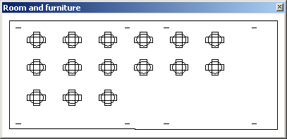
Those eight straight lines in the corners are columns. I should eliminate those. We don't want to move those around indiscriminately on a mobile device anyway, or the whole house might come crashing down around us.
Caveats
Rudolf Honke wrote in a reaction to my plan described last time:
You say that you want to avoid redundant geometry data in your cloud project:
As you know, it is possible to modify the geometry of an individual family instance by cutting voids off it. The geometry of such an instance differs from other ones.
As far as I remember, modifying instance geometry this way has been possible since Revit 2012 or so; the API 2013 says:
"FamilyInstance.GetOriginalGeometry: Returns the original geometry of the instance, before the instance is modified by joins, cuts, coping, extensions, or other post-processing."
Thus, there are at least three groups of elements to be handled:
- Individual elements, such as walls – have individual geometry, cannot be reused
- Family instances which have not been modified – can be instantiated, geometry is reusable
- Family instances which are post-processed, resulting in individual geometry – not reusable
In this case, I am only handling furniture and equipment instances that I do not expect to be modified.
After all, the plan is to move them around in the room, so they have to be free of constraints for it to work.
Still, these considerations obviously have to be taken into account for other applications.
Download
To wrap this up for the moment, here is GeoSnoopSymbols.zip containing the complete source code, Visual Studio solution and add-in manifest of the current state of this external command.
Next Steps
My next steps will be:
- Migrate this add-in from Revit 2013 to 2014.
- Implement server-side generated SVG code to display the room and furniture plan in CouchDB using Kanso.
- Implement editing of SVG on the mobile device and reflect changes back to CouchDB (I know how now).
- Implement Idling event handler and polling of CouchDB in the desktop add-in to reflect the changes back to the BIM in real-time.
- Implement an external application wrapper for the add-in providing four commands:
- Upload to cloud
- Refresh from cloud
- Subscribe to cloud
- Unsubscribe from cloud
I know exactly how to address all these points now, no exceptions left. Yay!
I look forward to hearing your comments and suggestions.