Beam Bottom Endpoint
Here is a nice little example illustrating different approaches to find the end point of the bottom centre line of an inclined beam.
Question: I am trying to find the coordinates of the end points of the bottom centre line of an inclined beam. Depending on the beam angle, these coordinates will change.
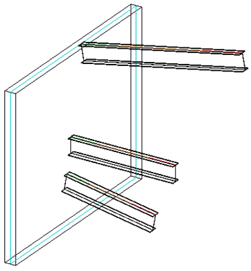
Here is a 3D view of the kind of situation I am looking at:
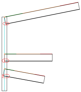
The front view looks like this with the beam end points marked in orange. The desired bottom line end points are marked by red points within the circled areas:
I am currently using the following code to retrieve the beam location line start and end points:
  LocationCurve location = beam.Location as LocationCurve;
  Curve c = location.Curve;
  XYZ p = c.get_EndPoint( 0 );
  XYZ q = c.get_EndPoint( 1 );
Answer: There are an infinite number of ways to achieve this. Here are three to start with, in order of increasing purely personal preference:
Face Iteration and Project
One way to approach this is to use the beam solid faces and projection methods provided by the Revit geometry API to calculate the desired points.You can determine the bottom face of the beam by querying the beam for its solid, iterating over its faces, and searching for the face whose normal vector has a minimal Z value, i.e. points downward the most. I provided source code samples implementing this for the bottom and top faces of a wall.
You can then project the beam location line end points onto that face using the Face.Project method to obtain the desired bottom line end points.
Parameter Values and Trigonometry
A second solution is based on querying some of the beam parameter values and using a little bit of trigonometry.
It calculates the sides of the right angle triangle using the beam direction vector, vertical delta and insertion value and returns the beam bottom coordinate as follows in C#:
void GetBeamInsertionAndVertDelta(
  Element beam,
  double sideLength,
  out double beamInsertion,
  out double beamVertDelta )
{
  // sideLength is beam height.
  // If there is any other element like plate to
  // be attached to beam bottom then
  // sideLength = beam height + plate thickness

  beamInsertion = 0.0;
  beamVertDelta = 0.0;

  if( null != beam && _eps < Math.Abs( sideLength ) )
  {
    Parameter cutLength = beam.get_Parameter(
      BuiltInParameter.STRUCTURAL_FRAME_CUT_LENGTH );

    Parameter stOffset = beam.get_Parameter(
      BuiltInParameter.STRUCTURAL_BEAM_END0_ELEVATION );

    Parameter endOffset = beam.get_Parameter(
      BuiltInParameter.STRUCTURAL_BEAM_END1_ELEVATION );

    double hypotenuse = cutLength.AsDouble();

    double side = Math.Abs( stOffset.AsDouble()
      - endOffset.AsDouble() );

    double angle = Math.Acos( side / hypotenuse );

    beamInsertion = ( sideLength / Math.Tan( angle ) );
    beamVertDelta = ( sideLength / Math.Sin( angle ) );
  }
}
Perpendicular Vector
The simplest solution may possibly be to avoid using the beam geometry as well as the tan and sin functions and just calculate straight away based on the beam location line.
You can determine the vector perpendicular to the beam location line and pointing downward as much as possible, i.e. lying in the plane P defined by the (non-vertical!) location line and the global Z axis.
Let's say the beam location line top two endpoints are stored in 'p' and 'q'. To determine the bottom points, we just need to know the height 'h' of the beam cross section and calculate a vector 'v' of length 'h' pointing downward and perpendicular to the beam location line. The desired points are given by p + v and q + v.
I used a similar calculation to determine the wall width or thickness vector 'w' to display the wall compound layers, except that it is horizontal, i.e. has a zero Z component, instead of lying in the plane P, with a minimal (negative) Z component.
Something like this untested snippet should do the job, given the beam location curve start point 'p', end point 'q' and height 'h' as defined above:
  XYZ u = q - p;
  XYZ w = XYZ.BasisZ.Cross( u );
  XYZ v = h * w.Cross( u ).Normalized;
As said, the desired points are then given by p + v and q + v.
Determine Hosted Family Host Type
On a different topic, in his latest AEC DevBlog post, Saikat Bhattacharya explains how you can determine the base host type of a hosted family via the Host parameter on the family document owner family property, which stores the following integer values corresponding to the FamilyHostingBehavior enumeration:
- None
- Wall
- Floor
- Ceiling
- Roof
- Face
The parameter value is zero, i.e. None, for families created using line and pattern based templates, so their host type cannot be determined using this method.
Note that if you have a face-based family instance, you can query its Host and HostFace properties to retrieve the host element and a reference to the hosting face, respectively.
Two more interesting methods to explore in this context are the FamilyCanConvertToFaceHostBased and ConvertFamilyToFaceHostBased methods provided by the FamilyUtils class.