Sweep PickPath Tolerance Criteria
Here is a rather specialised and hitherto undocumented topic of great importance to anyone trying to model precise complex swept geometry.
The issues below arose exploring the tolerance requirements of the 'Pick Path' options in the Revit UI, which map to the ReferenceArray and Reference input to the two FamilyItemFactory API calls for generating this kind of geometry:
Sweep NewSweep(
  bool isSolid,
  ReferenceArray path,
  SweepProfile profile,
  int profileLocationCurveIndex,
  ProfilePlaneLocation profilePlaneLocation );

SweptBlend NewSweptBlend(
  bool isSolid,
  Reference path,
  SweepProfile bottomProfile,
  SweepProfile topProfile );
It required quite a bit of research to resolve, both by the Revit development team and most of all by Bill Adkison of MarinCAD Custom Software Engineering, who is using this to create detailed furniture families like this:
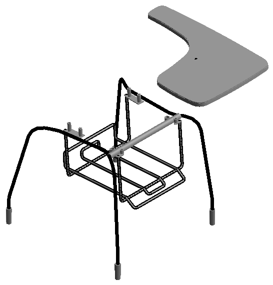
Bill ran into a number of issues creating these very precise and detailed sweeps.
Here is an example of some of the ensuing discussions and results:
Question: I have problems with sweeps created via PickPath.
I am creating many successful pickpath sweeps. However, in some cases, pickpath sweeps are failing with a MemoryAccessViolation.
One example has two model lines which can each be selected to create a PickPath sweep, but when both are selected together, the sweep fails. I have confirmed that their endpoints meet up. One curve is a Hermite spline, the other a line. When I convert the spline to a set of line segments connecting the fit points, it works. What is the problem with connecting these two curves into a common sweep pattern? They fail interactively as well as via API. This is still basically a programming problem, because I need to know the criteria for when attaching splines and arcs will work. In another case of failure, a model line and a model arc of short radius: 0.34 inches, and included arc of .61 radians, so the ultimate arc length is .224 inches, well above the 1/32" Revit precision threshold. You can sweep these curves independently, but they do not sweep when picked together. In the debugger, their endpoints line up.
Answer: There is a small gap between the line and arc in the model that causes the problems for that sweep path. Such gaps should be avoided.
Other conditions to watch out for are curves that are nearly tangent, but not quite tangent, or arcs with very large radii that are nearly indistinguishable from lines.
Here are some internal observations which may help give an idea of what is going on:
1. CollectPath3dCurveGRefs complains about the gap between the line and arc in the model. The gap has size about 9.8e-6, but that function uses DOUBLE_EPS (= 1.0e-9) as a point-to-point tolerance. It issues a DBG_WARN but returns ERR_SUCCESS when it finds a gap.
The unit tangents of the line and arc at the point where they (nearly) meet differ by about 0.002 in the z-coordinate (and somewhat less than that in the y-coordinate). Apparently, Revit can bridge huge angles in lines, while being rather intolerant of even small angles in other areas.
CreateSweptSolid calls fixGapsInSweepPath, which calls trimCurvesToNbrs, but the latter function uses sqrt(0.1)*DOUBLE_EPS as a point-to-point tolerance, so it considers the gap to need "repair". It attempts to intersect the line and the arc, but that ultimately calls circXLine2d, which uses DOUBLE_EPS as a tolerance, so that function does not find an intersection. TrimCurvesToNbrs therefore does not modify the path (i.e., it does not "fix" the gap). It does check that the result is continuous to within a certain tolerance, but it uses the vertex tolerance for that check, and this gap is smaller than the vertex tolerance (which is about 0.0005).
CreateSweptSolid ultimately fails because getCornerTurningTrf fails when finding the corner-turning transform from the line to the arc, because vecAlmostEqual(cornerPnt1, cornerPnt2) is false. This essentially uses DOUBLE_EPS as a point-to-point tolerance. I confirmed that avoiding that rejection in the debugger allows the swept solid to be constructed successfully. Nevertheless, such gap and lack of tangency should be avoided whenever possible.
2. In the model, the line and the Hermite spline are not accurately tangent. Their tangent vectors at the point where the curves meet differ by about 0.01 in one of the coordinates; they meet at an angle of about 0.017 radians (= 1.02 degrees). While computing the mitre surface between the line and the spline, getMiterCurve then calls pathSegsAreNearlyTangent, but that uses a tolerance of one degree, so this case doesn't even meet the criterion for being nearly tangent. getMiterCurve then fails at the check for parallel normVec = (0.49, -0.85, 0.13) and planeNorm = (-0.86, -0.5, 0.0) (approximately).
PlaneNorm is the normal vector of the plane of the sweep path, as computed by getMiterCurve, while normVec was passed down from createSweepAlongCurve, where it was computed by a call to getRadii, which gets it directly from the sweep frame passed to createSweptSolid.
3. Please make the line accurately tangent to the spline in the example. They meet at an angle slightly greater than one degree.
Of course, making the line accurately tangent to the spline is a difficult numerical problem, and will involve modifying both curves, which are in different planes, which will also have to be modified. Alternatively, one could recognize the situation and either break the sweep, or go back to all line segments.
4. Please make analytic computations (i.e., those involving lines, arcs, planes, and other simple curves or surfaces as accurate as possible for double-precision floating-point computations. In such cases, values that would ideally be equal should be considerably less than 1.0e-9. In general, Revit expects points that are ideally coincident to have a distance considerably less than about 1/160". In some cases, though, Revit code demands a tighter tolerance. Curves that are ideally tangent should have an angle at most 0.1 degrees.
The failure to create a sweep for the line/spline path in the sample with a circular profile of radius about 0.4329 might be fixed by making the line tangent to the spline.
5. There seem to be a number of hardcoded almost vertical and almost unit vectors in your code.
Revit definitely does not like slightly off-axis lines and planes.
It will certainly help stability if you can replace all vectors like the following one by the almost identical ones aligned with the cardinal axes:
  XYZ normalizedMajorAxis
    = new XYZ( 1.0,
      -0.00000000000024924835886401896,
      0.0000000000000012680828609390458 );
Specifying very slightly off-axis data is just asking for trouble. Do you really need to model anything that absolutely has to be so slightly off-axis? Is rounding an option for the input data you provide? This is not hard, once you are aware of the issue.
Response: 1. Details such as the point-to-point tolerance is exactly the kind of information I am looking for.
The gap in my data is a somewhat bigger than I expected, so I will write code to re-close them after my Revit computations are finished.
Does the fact that the tangents differ by this amount matter, i.e. cause the failure? Sweep handles 90-degree corners for line segments. Do non-lines have to have matching tangents? If so, that is great to know, as well as utterly unobvious. I can take evasive action if the tangents must match.
What is 'the vertex tolerance' exactly, in contrast to 'point to point'? For use by sweeps or path validation after the basic point to point? Is it used for Angles? Should I just be concerned with the DOUBLE_EPS distance for this problem?
2. So you require tangency for connecting PickPath segments that aren't lines? That is good to know. As noted earlier, because PickPath works with corners between lines, I assumed there was no tangent requirement for connecting elements, nor did I see any in the documentation. So to clarify the rules: must connecting PickPath elements have shared tangents at their connection point, UNLESS they are bound line segments? Here is the current list of possibilities:
- Line – Line: no tangency requirements.
- Line – Spline: tangency required.
- Line – Arc: tangent required or no?
- Spline – Arc: ?
- Spline – Spline: ?
- Spline – Arc: ?
If tangency requirements are a problem, I will correct them if possible, or revert to line segments.
I updated my logic to detect gaps and tangential inequality at connection points of multi-curve PickPaths, leading to the key logic summarised in the following code:
  /// <summary>
  /// Revit angle tolerance: 1 degree
  /// has been shown to be stable.
  /// </summary>
  const double kRevitAngleTolerance = Math.PI / 180.0;

  XYZ curCurveStartPt = null; // from current curve
  XYZ prevCurveEndPt = null; // from previous curve or null
  XYZ shiftVector = null;

  // Use DOUBLE_EPS tolerance in IsAlmostEqualTo
  // for legitimate endpoint proximity.

  bool shiftCurve = ( prevCurveEndPt != null )
    && !curCurveStartPt.IsAlmostEqualTo(
      prevCurveEndPt );

  if( shiftCurve )
  {
    // This case very rarely triggers.

    shiftVector = curCurveStartPt.Subtract(
      prevCurveEndPt );
  }

  XYZ nextCurveStartTan = null; // from next curve or null
  bool nextCurveIsLine = null; // from next curve, if any

  XYZ curCurveEndTan = null; // from current curve
  bool curCurveIsLine = null; // from current curve

  double epsTanAngle = nextCurveStartTan.AngleTo(
    curCurveEndTan );

  // Use cited tolerance of 1 degree between
  // connecting endpoint tangent vectors.
  // I actually experimented with up to 5 degrees,
  // and although I observed cases of tangent
  // differences of at least 2.6 degrees to
  // successfully sweep, sometimes it works and
  // sometimes it excepts.
  // 1 degree has held up well so far;
  // I have no known failures with it.
  // But the result is annoying notches in Revit
  // in places where AutoCAD sweeps can handle
  // the same curves automatically.

  bool writeSweepNow = false;

  if( ( nextCurveStartTan != null )
    // connecting lines have unequal
    // tangents but work in Revit.
    && ( !curCurveIsLine || !nextCurveIsLine )
    && ( epsTanAngle > kRevitAngleTolerance ) )
  {
    // Break off sweep and start a new one;
    // when tangent angles exceed this,
    // the sweep can except.

    // Final code to tweak current curve tangents
    // would go here; this is a big project in itself.

    writeSweepNow = true;
  }

  // if (shiftCurve)

  // Current curve is re-read, with shift in
  // location set in shiftVector.
  // Append current curve to model and record its
  // references in current curve reference array.

  // if (writeSweepNow)

  // Sweep is written with current curve, and new
  // Sweep begins with the next curve.
  // Loop until all curves are accumulated,
  // then write final sweep.
This eliminates all the failures due to connecting multiple curves in PickPath sweep creation.
MEP Calculations
A second question was raised on another rather specialised calculation topic:
Question: Can you point to any documents describing the Revit MEP calculation methodology?
Answer: The MEP calculations are described in the Revit WikiHelp Reference.
You can also look at Martin Schmid's Autodesk University 2010 classes ME330-3 Calculations in Revit MEP, primarily focused on duct and pipe, and ME231-2 Categorically, Demand It on Your Schedule: You Con-Du-It in Revit MEP, with a focus on electrical calculation. The former includes a video recording.
The Hub Class
Saikat Bhattacharya published an article taking a look at the Revit API Hub class, never before mentioned here. It lives in the Autodesk.Revit.DB.Structure namespace and is derived from the base Element class. It represents a connection between two or more Revit Elements, avoiding the need to connect them with each other directly. They each refer to the hub, which manages all the connectivity information for them. Its interface is pretty minimal; the only members not inherited from Element appear to be:
- GetHubConnectorManager to retrieve the hub ConnectorManager.
- HasOrigin to indicate whether the hub has a specific location in 3D space.
- GetOrigin to retrieve the hub 3D position, if it has one.
Saikat presents a sample code snippet showing how to access the elements connected to a given hub.
Leaving the Unshaved
I shaved again, after a couple of weeks of abstinence. Here is a last parting shot before leaving the unshaved masses, and afterwards:

Note the prow of a boat sticking out of the wall in the left-hand picture... where was this photo taken, please?